Gas Injection (gasInjection.pre)
Keywords:
-
hydrodynamics, vacuum, boundary
Problem description
This problem not only demonstrates the time-dependent boundary condition capabilities in USim, but also the ability to handle extremely strong shocks in 3 dimensions. In this case, the injected fluid is 6 orders of magnitude more dense than the background gas.
Creating the run space
The Gas Injection example is accessed from within USimComposer by the following actions:
- Select the New from Template menu item in the File menu.
- In the resulting New from Template dialog, expand USimBase: Basic Physics Capabilities.
- Select Gas Injection and press the Choose button.
- In the Choose a name for the new runspace dialog, press the Save button to create a copy of this example in your run area.
- Press the Save And Process Setup button in the upper right corner of the Editor pane.
The basic example variables are editable in the Editor pane of the Setup window. After any change is made, the Save and Process Setup button must be pressed again before a new run commences.
Input file features
The input file allows the user to set the jet pressure (PRESSURE), the jet mass density (RHO), the jet flow velocity (U), the cfl number (CFL), the end time (TEND), and the number of data dumps (NUMDUMPS).
Primary variables are:
- PRESSURE - Pressure in Jet.
- RHO - Mass density of jet.
- U - Velocity of jet.
- CFL - CFL number.
- TEND - Simulation end time (seconds).
- NUMDUMPS - Number of data dumps during the simulation
Running the simulation
After performing the above actions, continue as follows:
- Proceed to the Run window as instructed by pressing the Run icon in the workflow panel.
- To run the simulation, click on the Run button in the upper right corner of the Logs and Output Files pane.
You will also see the engine log output in the Logs and Output Files pane. The run has completed when you see the output, “Engine completed successfully.”
Visualizing the results
After performing the above actions, continue as follows:
- Proceed to the Visualize window as instructed by pressing the Visualize icon in the workflow panel.
- Press the Open button to begin visualizing.
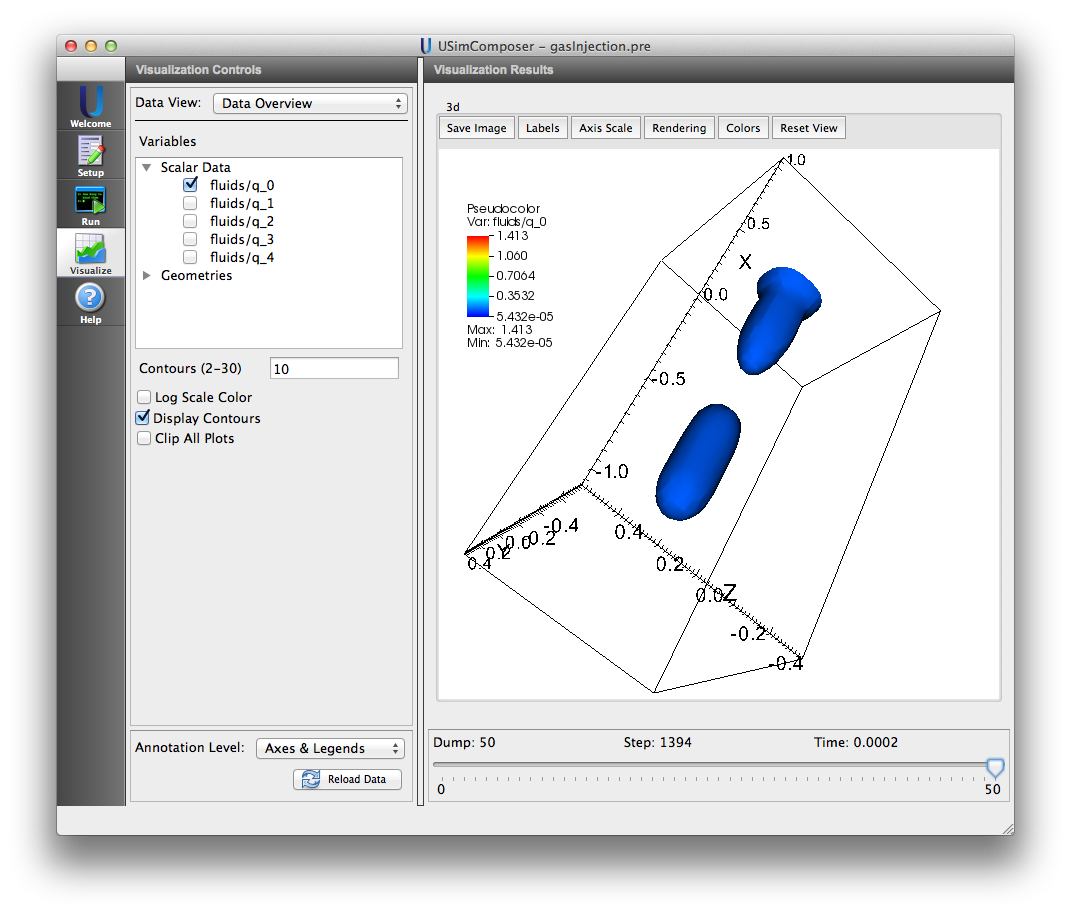
- To visualize the fluid density, expand the Scalar Data tab and click the check box for fluids/q_0.
- Click the check box for Display Contours.
- Use the mouse to rotate the image within the Visualization Results pane.
- Drag the slider at the bottom of the visualization window to move through the simulation in time. The mass density distribution at the end of the simulation is shown in Fig. 86.
Note that \(q_0\) is mass density, \(q_1\), \(q_2\), and \(q_3\) are the three components of momentum density, and \(q_4\) is energy density.
Further experiments
- Set U to 100.0 and increase TEND by a factor of 10 to see the effect of mach number on jet expansion.
