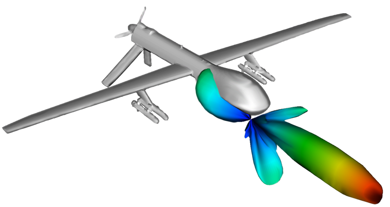
Antenna on Predator Drone
This problem illustrates how to obtain the far-field radiation patterns of a current source antenna mounted on a Predator Drone.

2.4 GHz Yagi Uda Antenna
This example illustrates how to obtain the far field radiation pattern of a Yagi-Uda array.

Antenna Array 2D
This set of 2-D VSimEM simulations shows how to obtain the far fields, S11 parameter, gain, and phase shift of a one-element antenna as well as the far fields, gain, S parameters, and phase shift of a multiple-element antenna array with one excited element

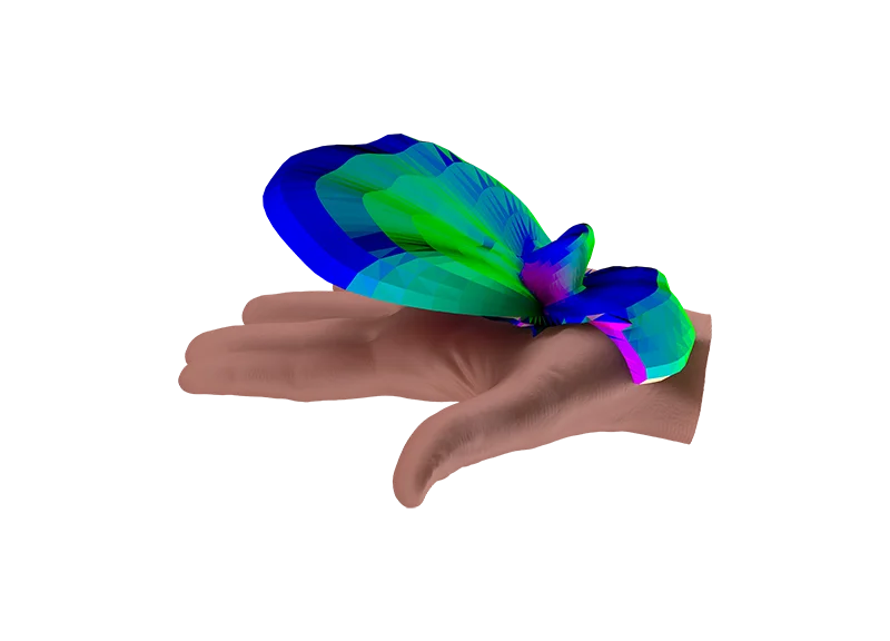
Antenna on Human Hand with Dielectric
This problem calculates the far-field radiation pattern of a small wifi antenna. The fields interact with the human hand for which the bone structure was approximated by long thin cylinders.

Loop Antenna from a Coaxial Cable
This example illustrates how to use the coaxial cable Field Boundary Condition and Constructive Solid Geometry to create a coaxial loop antenna.

Dipole Antenna
Excite the antenna and watch the dipole electromagnetic radiation emanate from the antenna.

Dipole Above Conducting Plane
This problem illustrates how to obtain far fields within VSim by simulating an infinitesimally short dipole mounted a variable height above a conducting plane.

Dish Antenna
The Dish Antenna simulation illustrates how to get the radiation pattern from a source in the presence of a complex shape.

Half-Wave Dipole in Free Space
This problem illustrates how to obtain far field radiation patterns from VSim simulation data. The simulation itself consists of a half-wavelength long current source in free space.

Horn Antenna
This example illustrates how to obtain the far field radiation pattern of a sectoral horn antenna.

Patch Antenna Far Field
This problem takes the same patch antenna from the Patch Antenna example and modifies it to calculate the far-field radiation pattern.

Phased Array Antenna
This VSimEM example illustrates how to setup a phased array simulation and analyze the far field results

Dipole Radiation
The dipole moment oscillates with a given frequency which then results in electromagnetic radiation being emitted at the same frequency.