Circuit Shielding
Keywords:
-
radiation, GRAS, shielding, Total Ionizing Dose
Problem Description
This problem demonstrates how the Total Ionizing Dose on an integrated circuit may be reduced through the use of boron shielding.
To do this three simplified integrated circuits, modeled as aluminum boxes are placed on a silicon substrate. Above two of the aluminum boxes, a thin and a thick box of boron is placed to act as a shield.
Opening the Simulation
The Sensitive Circuit example is accessed from within RSimComposer by the following actions:
- Select the New → From Example… menu item in the File menu.
- In the resulting Examples window expand the RSim for Basic Radiation option.
- Expand the Basic Examples option.
- Select Circuit Shielding and press the Choose button.
- In the resulting dialog, create a New Folder if desired, and press the Save button to create a copy of this example.
All of the properties and values that create the simulation are now available
in the Setup Window as shown in sensitivecircuitsetupwingras.
You can expand the tree elements and navigate through the
various properties, making any changes you desire. The right pane shows a 3D
view of the geometry, if any, as well as the grid, if actively shown.
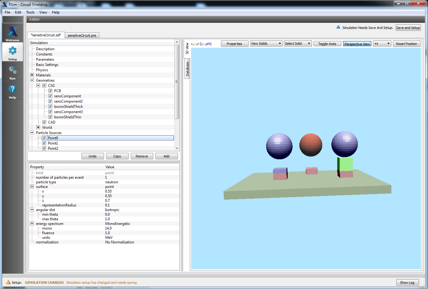
Setup Window for the Sensitive Circuit example. The PCB is colored green, the aluminum IC models red, and boron shields green
Simulation Properties
This example demonstrates how Total Ionizing Dose is impacted by the thickness of a boron shield.
Under the Basic Settings tab the number of events to be simulated can be selected, as well as the simulation model. Right now the only supported model is gras.
The Shielding physics list is used for this simulation, with GEANT4 standard cuts at 0.7 um.
Three point particle sources are placed above our three test coupons, which are on the PCB substrate. Each particle source has only a 1 degree angular distribution in order to prevent them from interfering with each other. Remember that zero degrees corresponds to the negative Z direction. The neutrons are emitted at a monoenergetic 14 MeV with no normalization.
A total ionizing dose tally, along with a fluence tally is placed for each of the three sensitive componeents.
Running the Simulation
After performing the above actions, continue as follows:
- Proceed to the Run Window by pressing the Run button in the left column of buttons.
- To run the file, click on the Run button in the upper left corner of the Logs and Output Files pane. You will see the output of the run in the right pane. The run has completed when you see the output, “Engine completed successfully.” This is shown in
sensitivecircuitrunwingras.
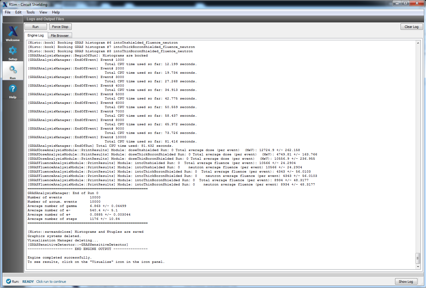
The Run Window at the end of execution.
Visualizing the Results
Direct visualization of results is not possible in RSim1.0
Further Experiments
As can be shown from the results, a 3 cm thick layer of Boron results in a 17% reduction in the Total Ionizing Dose, while a 10 cm thick layer yields a 61% reduction.
By changing the material used, this reduction in TID can be changed.