Setup Window for Simulations
After you open a new or example simulation , RSim displays the Setup window containing a Editor pane with a Simulation Elements Tree, a Property Editor, and a Geometry View to allow for easy creation of your simulation. The icon panel remains available on the far left.
Note
A Navigation Pane can be shown by clicking and dragging on the vertical bar separating the Icon panel from the Editor pane.
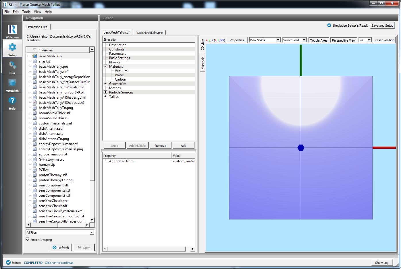
Fig. 30 The Navigation Pane
The following sections will go through each of the components of the Setup window.
The figure Setup window illustrates the layout of the RSim Setup window using labels for the parts of the interface to which this introduction and the tutorials refer.
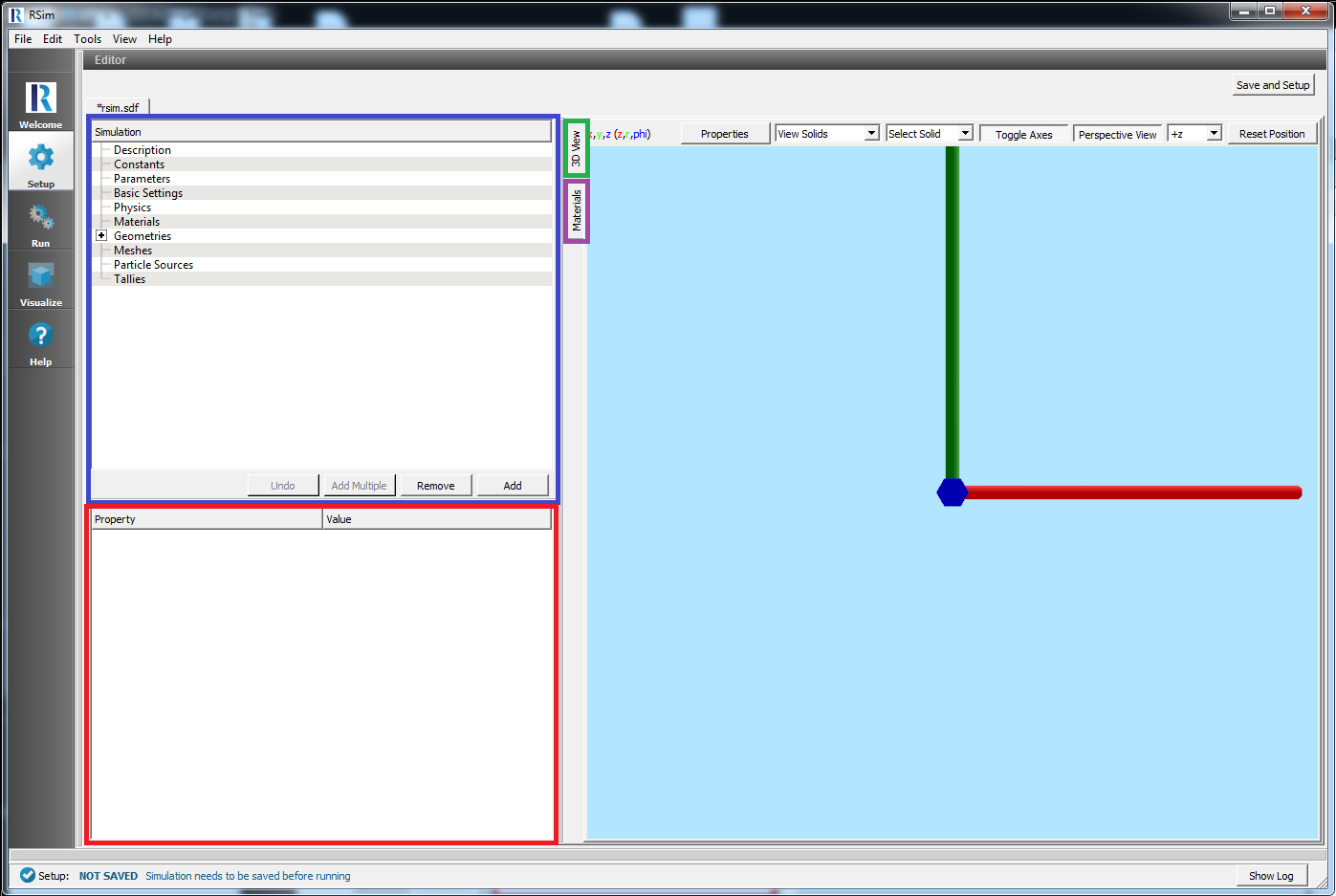
Fig. 31 Setup window
Elements Tree
You can navigate through the Elements Tree using either your mouse, or your keyboard arrows. The up and down arrows will scroll up and down through the list of elements, while the right and left arrows will respectively expand and collapse the elements. To double click, press F2.
Highlighting a particular element in the tree will cause the Property Editor to update with Property/Value pairs that can be edited.
New elements can be added under an element in the tree by Right Clicking. This will be context sensitive, so for example right clicking Particle Sources will open up a tree of all types of available particle sources to choose from. Select one and click on it to add a new instance of that element.
Turn Off/On
This is an option available after Right Clicking or using the Add button for elements that are not visualized in the 3D View. If it is selected it will gray out the element and it will not be translated into the input file.
This can be particularly useful for comparing results with and without a single element in place without having to go through the process of completely re-specifying it.
Buttons
Undo
This will Undo the last thing done. For example it will Undo the addition of an element, or the setting of a property.
Add Multiple
This is a shortcut that will add another instance of the last element added to the tree. Note that this can only be used on elements that are not visualized in the 3D view.
Remove
This will removed the highlighted element of the tree.
Add
This is the equivalent of right clicking a selected Element in the tree, and will present the same options.
Property Editor
The Property Editor allows for setting of specific properties under each of the Elements from the Elements Tree for the simulation. Such properties might include sizes in the X, Y, and Z directions, or the type of particles.
The Property and Value inputs are context-sensitive. The availability of a particular property may depend on other properties or selections of the Element Tree. For instance, changing the Energy Spectrum in the Particle Source element will bring up a new set of energy properties to be set.
Geometry View
The 3D View section can be used to view the simulation setup including the geometry, grid, and source.
Buttons
Properties
This allows for selection of the line width and point size, as well as how Colors will be assigned to shapes in the 3D View See Colors for further information.
View Solids
Select Solid
Toggle Axes
A toggle button to show or hide the axes.
Perspective View
Axis Drop-down Menu
Drop-down menu for choosing the axis from which the object is viewed.
Reset Position
Pressing this button will reset the camera view to be along the axis selected in the drop-down menu.
Navigating
Navigation in 3D space is possible under keyboard and mouse control.
Rotate
Holding down the right mouse button and dragging it will rotate the camera position around the object being viewed.
Pan
Holding down the left mouse button and the Shift key pans the view in a plane without rotating the viewed object.
Zoom
Using the mouse wheel, the view can be zoomed in or out. If the system does not have a mouse wheel, then holding down the left mouse button and the Control key and moving the mouse up and down will also zoom in and out.
Materials View
The Materials View is for viewing and adding materials to your simulation.
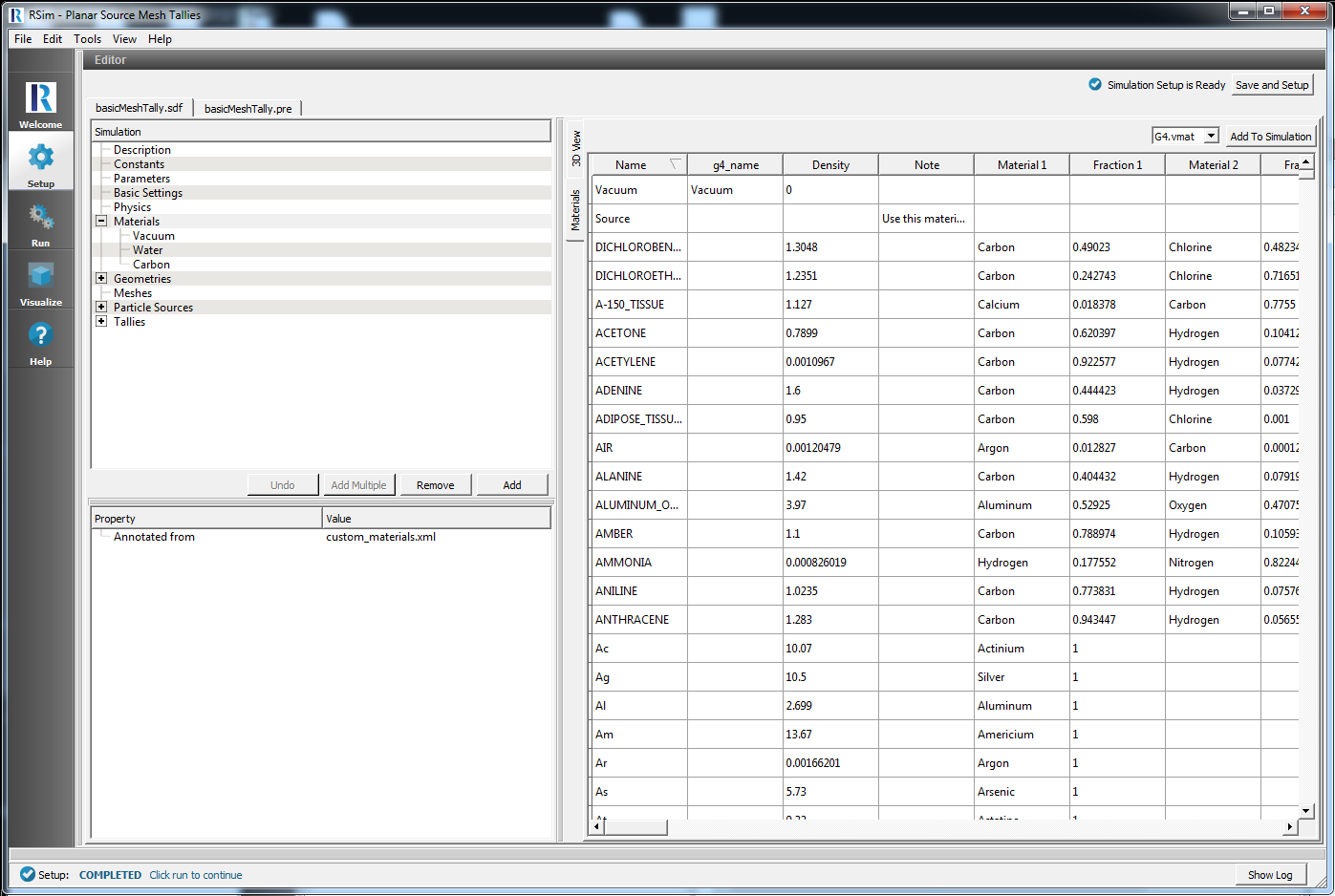
Fig. 32 The Materials view
You can add materials to your simulation by highlighting the particular material you are interested in, and then clicking on the Add to Simulation button.
For more information on materials, please see Materials.
Colors
Colors can be assigned to any Geometry in the 3D View
By default all Geometries are a default color, and can be changed by double clicking on the color property of the geometry. It is also possible to assign the color of geomtries based on the materials assigned. See Color Assignment By Material for details.
A preview of the actual color assigned to that geometry will be shown as the Value of the color property.
In addition to changing the color it is also possible to change the opacity of a geometry. The interface for changing the colors is different for each operating system and is described below.
Changing Colors on Windows and Linux
On windows a single dialog box is available, as shown in the image below.
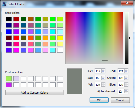
Fig. 33 The Color Selection Box
48 Pre-determined colors are available as Basic Colors
It is also possible to create a custom color by moving the black cursor in the box on the right side of the screen. A custom color may be saved as a preset option by clicking the Add to Custom Colors button. If added as a Custom Color it will be available in the 2 x 8 grid of Custom Colors across all simulations.
The opacity of the color can be changed by modifying the Alpha channel with 255 as minimum, and 0 as maximally opaque.
Click OK to accept the color.
Changing Colors on Mac
With a Mac the color may be selected from one of five dialog boxes. The default is the Color Wheel shown below.

Fig. 34 The Color Selection Box
A color may be selected by dragging the targeting reticle across the color wheel. Darkness is controlled on the slider beneath the wheel. Opacity may then be set between 0 and 100%.
To save the color as a custom color drag the large box on the left side of the dialog box to one of the 2 x 9 grid squares at the bottom of the dialog box.
Click OK to accept the color.
Color Assignment By Material
To assign colors of all objects based on the material used first click on the Properties button and select the Color by Property drop down menu. Then select material.
This will then change the color of all Geometries to the color specified by the color property of the Material assigned to that geometry.
The color of a material can be changed by clicking on the actual color shown as the Value of the material. This will then open a dialog box as described above based on operating system.
Note
If you change the color property of a specific geometry that color will overwrite the assigned color from the material. The color shown as the value for a geometry will not correspond to the color assigned to the material if colored by the material.