2D Magnetron (magnetron2D.sdf)
Keywords:
-
magnetron
Problem description
This VSimMD example simulates a rising sun magnetron in two dimensions. A load is added to one cavity, representing a coupler to the magnetron through the quality factor, Q. Upon configuring an electrostatic voltage across the anode and cathode, particles are introduced to the simulation, exhibiting a five spoke pi-mode.
This simulation can be performed with a VSimMD or VSimPD license.
Opening the Simulation
The 2D Magnetron example is accessed from within VSimComposer by the following actions:
- Select the New → From Example… menu item in the File menu.
- In the resulting Examples window expand the VSim for Microwave Devices option.
- Expand the Radiation Generation option.
- Select “2D Magnetron” and press the Choose button.
- In the resulting dialog, create a New Folder if desired, and press the Save button to create a copy of this example.
The Setup Window is now shown with all the implemented physics and geometries. See Fig. 427.
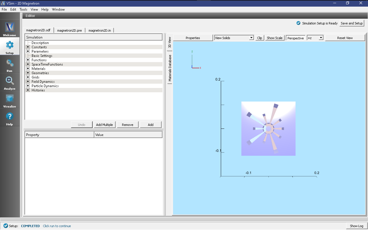
Fig. 427 Setup Window for the 2D Magnetron example.
Simulation Properties
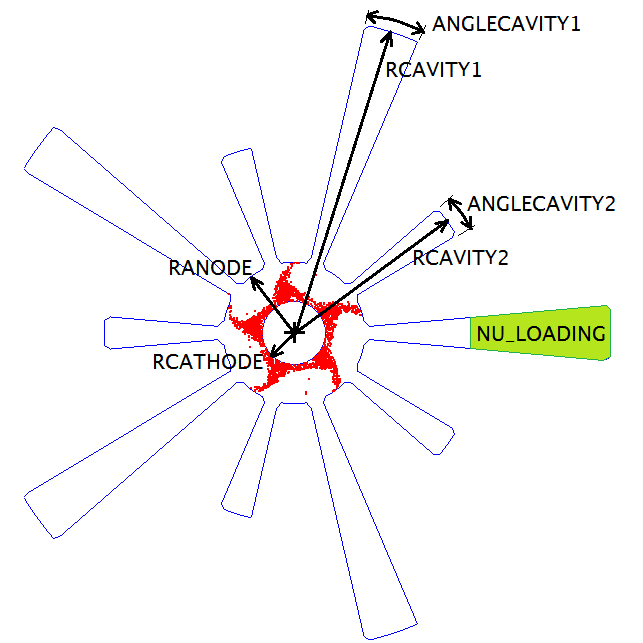
Fig. 428 Some exposed variables of the 2D Magnetron example.
As seen in Fig. 428 of the rising sun magnetron, the radius of the cathode is RCATHODE and the radius of the anode is RANODE. Long cavities have radius RCAVITY1 and opening angle ANGLECAVITY1. Short cavities have radius RCAVITY2 and opening angle ANGLECAVITY2. These dimensions control the spectrum and thus the operating frequency, which for the default parameters is approximately 960 MHz.
Running the simulation
After performing the above actions, continue as follows:
- Proceed to the Run Window by pressing the Run button in the left column of buttons.
- To run the file, click on the Run button in the upper left corner of the right pane. You will see the output of the run in the right pane. The run has completed when you see the output, “Engine completed successfully.” This is shown in Fig. 429 below.
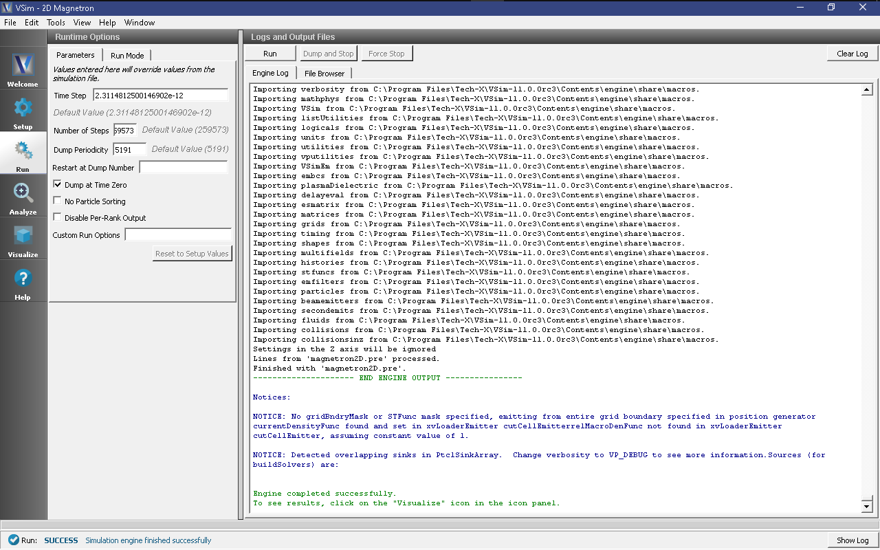
Fig. 429 The Run Window at the end of execution.
Visualizing the results
After performing the above actions, continue as follows:
- Proceed to the Visualize Window by pressing the Visualize button in the left column.
- Expand Particle Data
- Expand electrons
- Select electrons
- Expand Geometries
- Select poly (magnetron2DGeomSolid)
The electron modes can be viewed in the right pane. Use the dump slider on the bottom of the right pane to step through time. When electrons are emitted from the cathode, the four spoke, 650 MHz is present during startup. At approximately 250 ns, the five spoke begins to dominate and eventually appears as seen in Fig. 430.
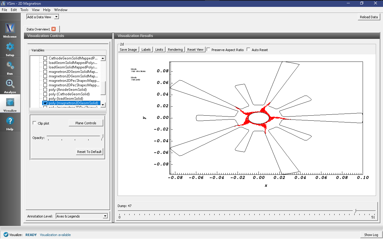
Fig. 430 The five spoke pi-mode at 600 ns.