Troubleshooting Visual Setup Crashes
The Visual Setup makes setting up simulations much simpler than writing an input
file, but the output messages when a simulation crashes can be mysterious. If a
simulation crashes before the engine takes the first step, it is more than likely
that there is an error in the .sdf file. Documented below are some common
errors, and the output messages they will create at runtime. If your simulation is
crashing before the first step, take a look to see if any of the error messages
shown below matches yours.
If your error message is NOT below, send an email to support@txcorp.com
and an Application Engineer will take a look at your simulation, and maybe your
error will show up in the documentation for the next release!
General Tips
- Check the
.infile for any unevaluated expressions. - The message “Object %%%%%%: Could not locate object * in the input file object hierarchy”
usually means that something is missing from the
.sdffile. Either a variable used in the simulation isn’t present or is miss-named, or an attribute isn’t set/is left blank. Try to figure out what the “%%%%%%” object is in the simulation then figure out what is missing. See below for some specific examples the examples. - Running in parallel can sometimes suppress error messages. If you get a crash try running in serial for a better error message.
- If a simulation with particles makes it to the first step, then hangs, it is possible that more particles than VSim can handle are being loaded into the simulation.
- Objects need to be assigned a material before they can be used else where in the simulation.
- Geometry objects cannot set boundary conditions on the walls of a simulation. That is, a boundary condition with the “boundary surface” attribute set to “shape surface” will fail to set a boundary on the upper x, lower x, upper y, etc surfaces of the simulation.
- When using a geometry object to set a boundary condition internal to the simulation boundaries, make the geometry extend beyond the nodes on which you wish to set the boundary.
Parameter/Constant Not Named Properly
The following error was created in a simulation that had a constant named BEAM_RADIUS but had a SpaceTimeFunction that used “BEAMRADIUS”.
Here, the unknown expression (“undefined symbol”) was printed out, providing an avenue for beginning the debugging process.
History Attribute Not Set
This error was from the same simulation as the error above. A history to count the number of physical particles was added, but the species was left blank.
Unlike the error above, there is no “ERROR: …” statement printed out. The nature of the error has been highlighted in the image below for visibility. Sometimes, the nature of the error can be buried in the output, so keep a sharp eye out for statements like the one below, because it does (indirectly) point to the cause of the crash.
Missing Attribute in Boundary Condition
This error is very similar to the one above (History Attribute Not Set). In this case a Dirichlet boundary condition named “dirichlet1” was added to the simulation, but a surface for the boundary condition was not specified.
The name of the boundary condition that was added was “dirichlet1”. In the image below, notice that this name appears in the error message (“Object dirichlet1Filler …”).
Over-Specifying Boundary Conditions
This error arose when two, overlapping CSG geometry objects were used to set the voltage on a region in the simulation, so the voltage was over-specified.
Depending on which electrostatic solver is being used, a different message will be output. The first error message below was the result when using the “superLU” direct solver:
This message was output when using the “gmres” iterative solver:
Under-Specifying Boundary Conditions
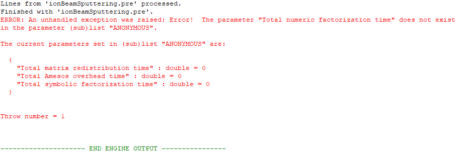
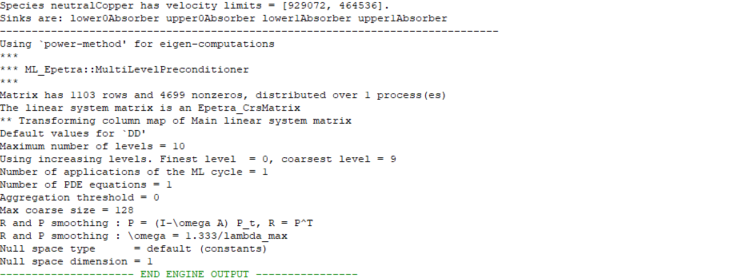
This is an example of an error where the printed error statement provided little to no help in debugging, unless you are deeply familiar with matrix solver packages (Epetra constructs matrices and is the part of the Trilinos Library which is used by VSim).
The cause of this error is that there are insufficient boundary conditions resulting in an in complete matrix. If you see this error, adjust your boundary conditions to make sure boundary conditions are completely set on all boundaries of the simulation Note: geometries cannot be used to set boundary conditions on the walls/boundaries (lower x, upper x, lower y, etc.) of a simulation.
Particle Loader Missing Loading Volume
Below is an example of what happens when a particle loader is not setup correctly. This is another more mysterious error message, since after the “ERROR: In Setting up simulation” there is very little to indicate the location of the bug. However, notice that the last thing printed before the error was “Sources are: /n particleLoader0”. This is a hint as to where to check your input file.
Fluid Missing Volume
This error is almost identical to the particle loader error listed above. A background fluid was added to the simulation, and the volume attribute was not set. Notice how the simulation crashes right after printing out a statement about the “neutralFluid1”.
Unable to Open SDF (No Such Attribute Error)
If after creating a simulation with an imported CAD file and changing the file import, it cannot reopen with an error “getAttrib const: No such attribute. Attributes are…” This can be caused by a CAD file with multiple parts having the same name, and then the number of parts with multiple names changing. For example if a single .step file is imported twice, and then a single deleted. This is due to an issue with how VSim handles parts with multiple identical names. It is not an issue if the number of imported CAD file’s stays consistent.
To correct this issue contact Tech-X Support.
Geometries Having Poor Lighting
If your simulation uses geometries or grids smaller than 1mm or larger than 100m, click the ‘Show Scale’ button in the 3D view and use the scale slider to select the appropriate scale for rendering. This will prevent issues with geometry visibility, axis labeling, and item coloring.


