Introduction to Parameter Scan
It is possible to run Parameter Scan (also known as Variable Sweep) through VSimComposer. You will be able to choose variable(s) and different values for them so that multiple simulations are run with the chosen values. In VSimComposer, each such simulation is called a sub simulation.
For the scan, You will be able to choose variables defined in the Elements Tree in visual setup and Editor Pane in the text-based setup. All User Defined Constants and Parameters that are not expressions (i.e. a constant) are eligible for the scan.
In the upcoming section, we will see how to run a parameter scan in VSimComposer. We will use an example Dipole Above Conducting Plane for the demonstration.
Using An Example To Demonstrate How To Run Parameter Scan
First open the Dipole Above Conducting Plane and follow along:
Select the New -> From Example menu item in the File menu.
In the resulting Examples window, expand the VSim for Electromagnetics option.
Expand the Antennas option.
Select Dipole Above Conducting Plane and press the Choose button.
In the resulting dialog, create a new folder if desired, and press the Save button to create a copy of this example in your run area.
This will open the Dipole Above Conducting Plane example.
Once the simulation is open and setup is completed, parameter scan can be performed by clicking on the Design icon from the icon panel (see Fig. 102).
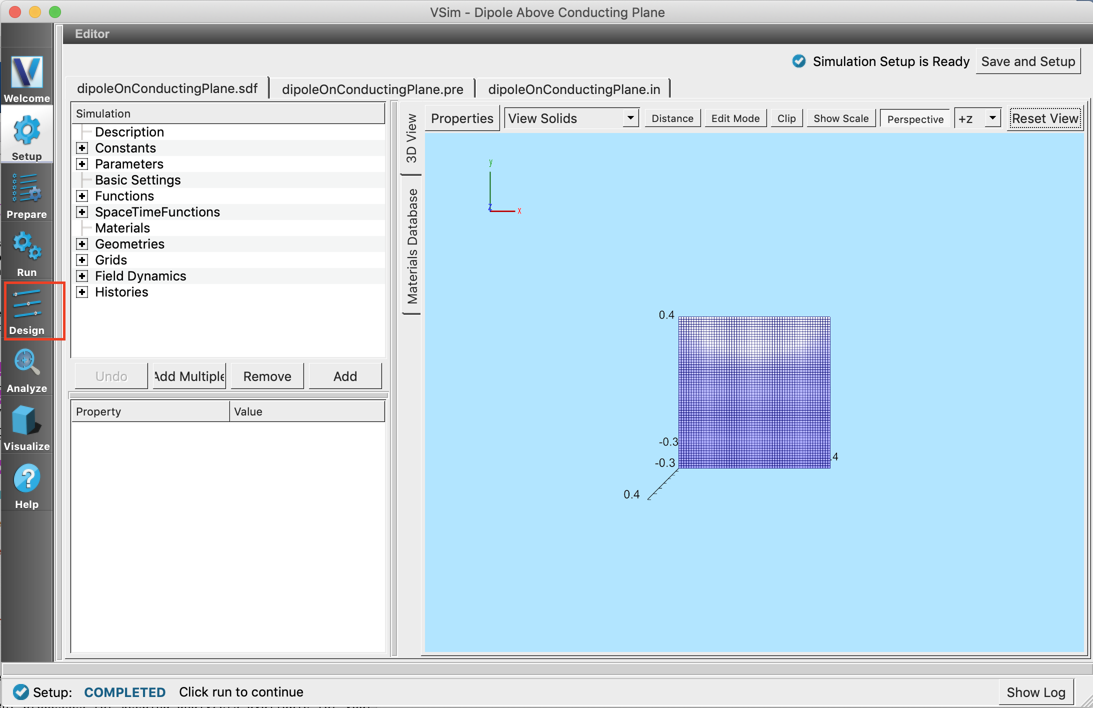
Fig. 102 Setup Window for Dipole Above Conducting Plane Example and Design Icon
Parameter Scan Panel
On clicking on the Design icon, the following Parameter Scan panel is visible.
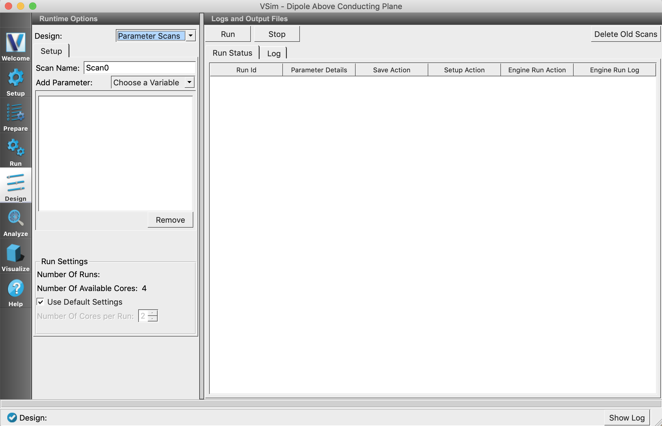
Fig. 103 Parameter Scan Panel
Setting up the Parameter Scan
The Runtime Options pane allows setting up the scan and the Logs and Outputs Files pane allows viewing the status and logs of a sub simulation run.
In Runtime Options pane, under the Setup tab, you will be able to set the name of the parameter scan. By default, the scan is named Scan0 but for this exercise let’s set it to testScan.
The Choose a Variable drop-down lets us add the variables for the scan. VSimComposer also supports scanning multiple variables at once. The chosen variables get added to the list below the drop down.
The variable specific options for each added variable in the list are available upon the selection and can be set individually. See Choosing Model And Values for the Variable.
For this example, Choose the variable HEIGHT.
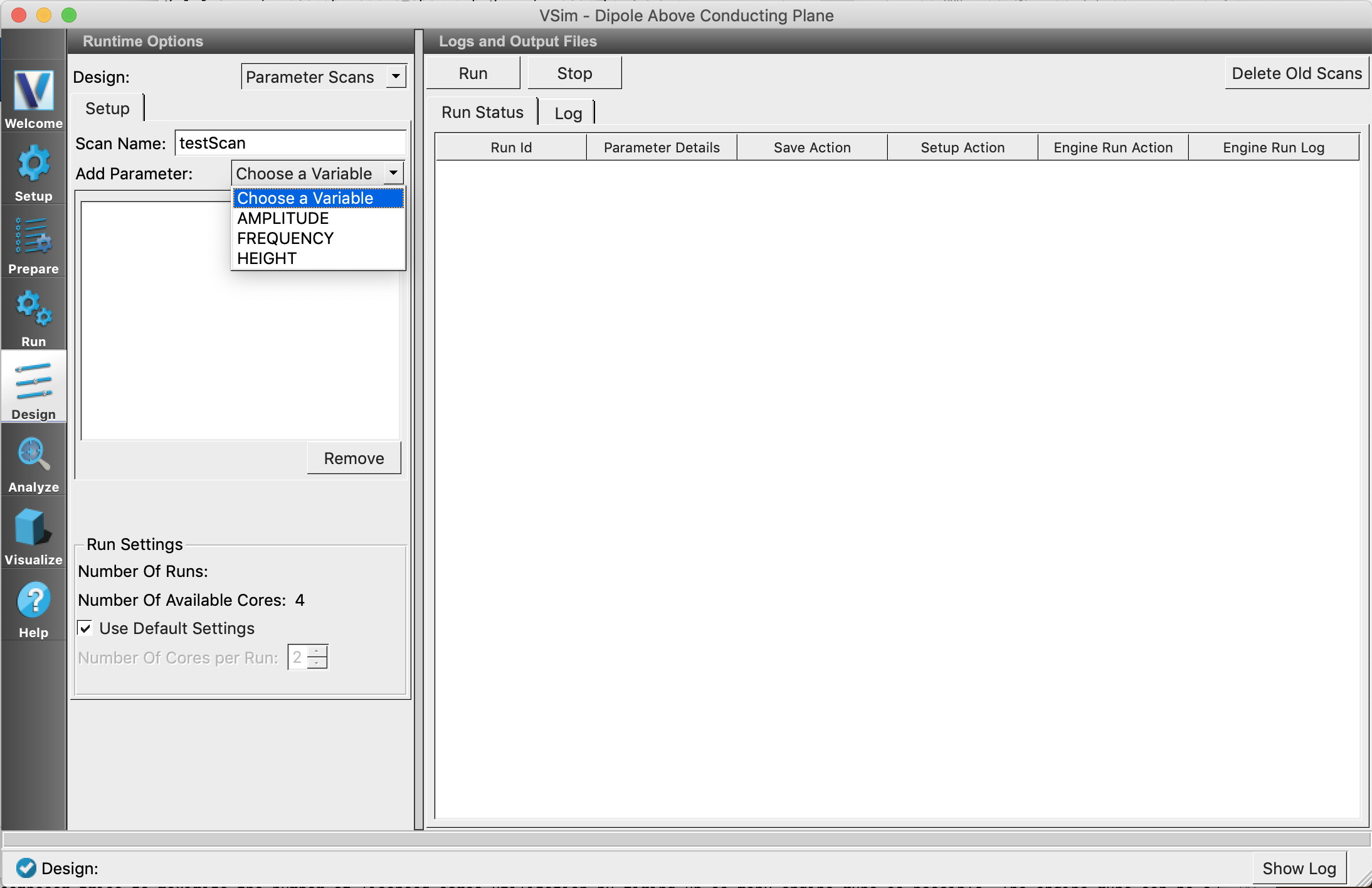
Fig. 104 Variable List
Choosing Model And Values for the Variable
The options below are available for each selected variable on the list.
Model Choice Allows selection of the Model. Model refers to the way a variable gets different values for the scan.
Range : This model calculates values within the specified range (inclusive). It has Number of Points (total number of values), Minimum (start value) and Maximum (end value) fields. Checking the Log Scale steps the variable in log scale. By Default, number of points is 1, minimum is the current value of the variable and maximum is a number greater than the minimum by an arbitrary amount.
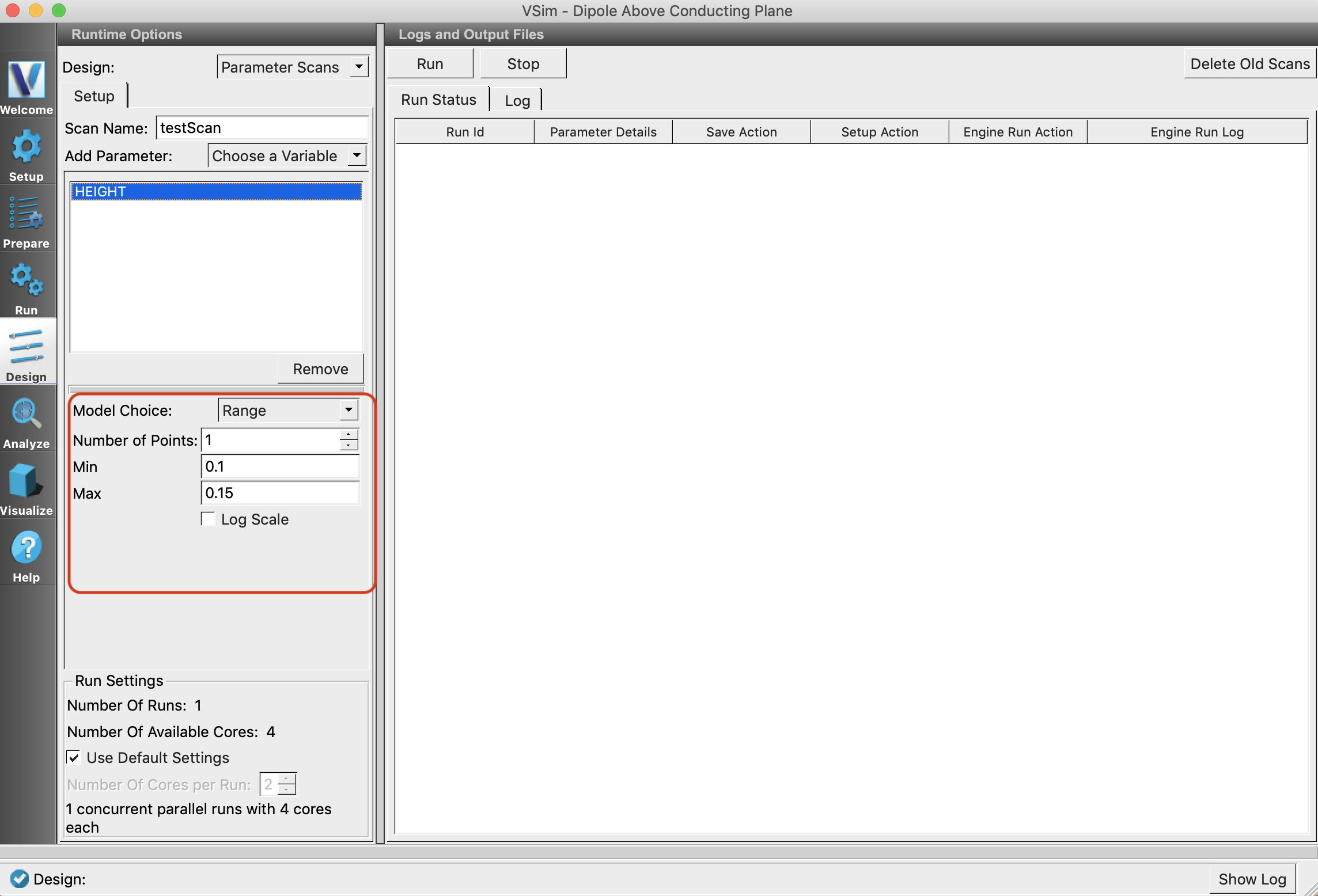
Fig. 105 Range Model
List : Assigns specified discrete values to the variables. There are no default values for list.
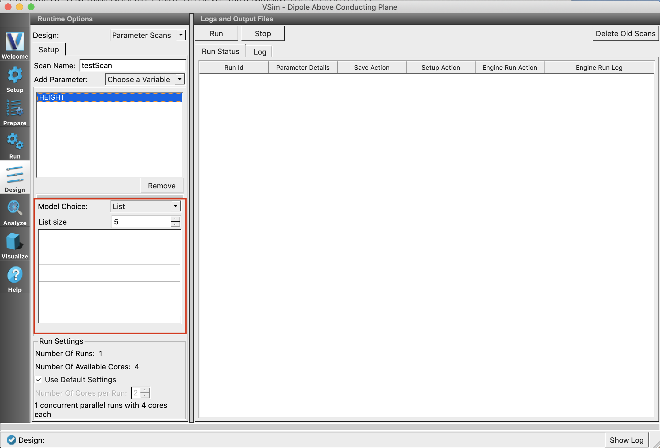
Fig. 106 List Model
For this simulation Choose Range as the model choice, set number of points to 3, mininum to 0.15 and maximum to 0.3. There will be three sub simulations.
Note
For Range model, the values can only be incremented so always make sure the start value is less than the end value.
Run Settings
The engine run parameters(Time Step, Dump Periodicity, Number of Steps) for each sub simulation are extracted from the Run Window. First we will define a few terms here and then see how the Run Settings option can be used.
Sequential Runs: Run each sub simulation sequentially, i.e out of n sub simulations only one will run at a time. Second run starts only after completion of the first.
Concurrent Runs: Sub simulations are run concurrently, i.e. m(<=n) number of sub simulations will run at a time.
Parallel Run: Run each sub simulation with mpiexec with certain -np value.
Serial Run: Run each sub simulation in serial.
By default, Use Default Settings is selected and VSimComposer tries to maximize the number of licensed cores utilization by running as many sub simulations as possible. Each run can be serial or parallel depending on total number of runs and number of available licensed cores.
Unchecking the Use Default Settings ignores the default behaviour and allows you to enter the number of cores you want to run each sub simulation with. The value can be entered in Number Of Cores per Run box and cannot exceed the total number of licensed cores. To maintain consistency, all the sub simulations will run with the same number of cores.
VSimComposer informs about the type of run through a text label below the Number Of Cores per Run box.
For our Dipole Above Conducting Plane example, we will proceed with the default.
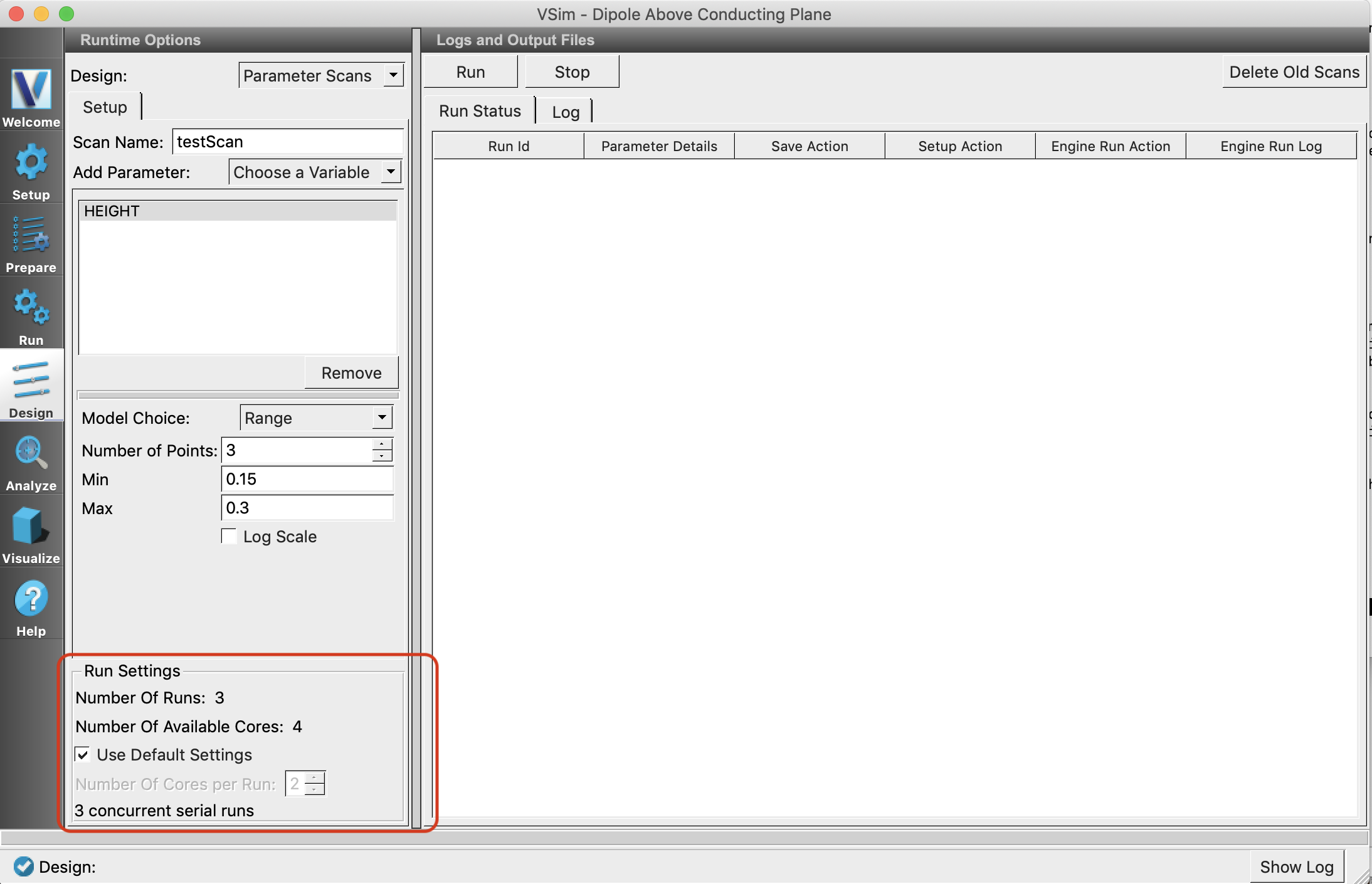
Fig. 107 Run Settings
Start/Stop the Scan
Click Run button to start the parameter scan. It can be stopped any time by clicking on Stop. On clicking Stop all the ongoing sub simulation runs are stopped and waiting runs will not be started.
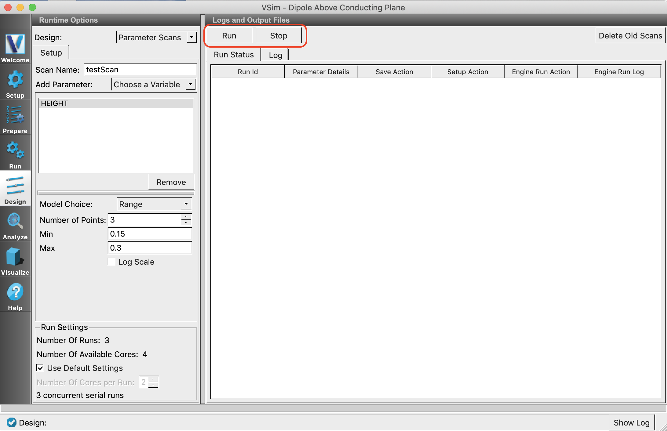
Fig. 108 Start and Stop
Output pane
Run Status Tab : This tab consists of a table that tracks the status of every step of each sub simulation. See Fig. 109. There are seven colums by default.
Run Id : Identification string for a sub simulation. Contains name of the scan and index of variables.
Parameter Details : Contains a button which when clicked, shows the variables and their values. See Fig. 110.
Save Action : Shows status of save action.
Setup Action : Shows status of setup action. This column is visible only in visual setup.
Engine Run Action : Shows status of engine run action.
Post Processing Action : Shows status of post process action. This column is visible only if any analyzer in the Analyze Window is marked to run automatically after each engine run.
Engine Run Log : Contains a button, which opens up a tab to view the log of the engine run.
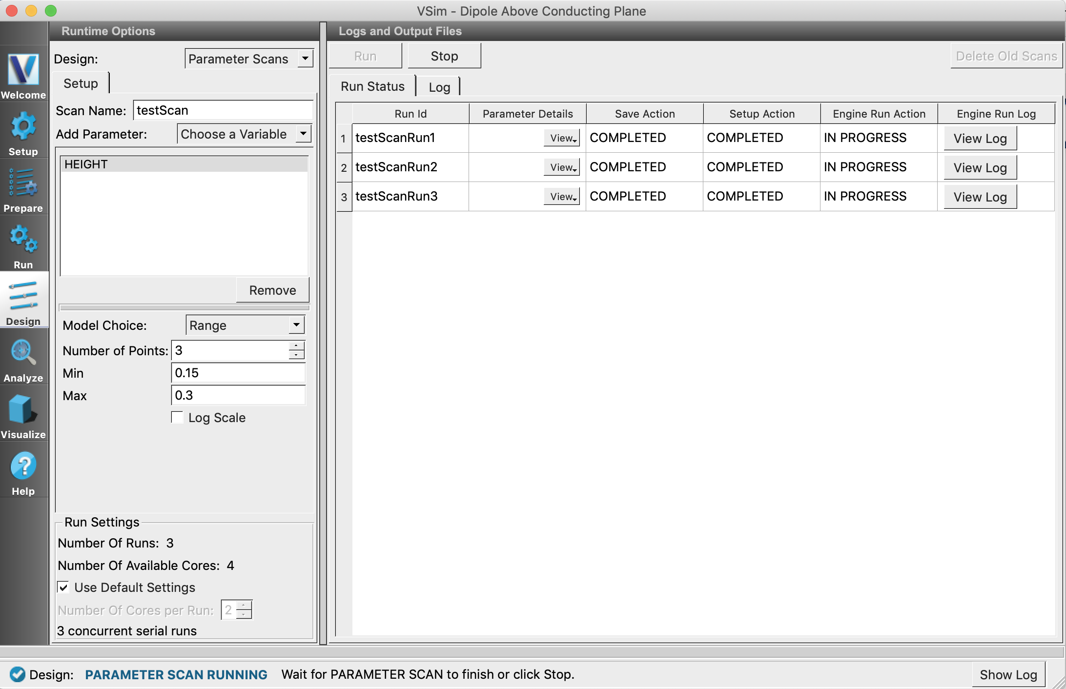
Fig. 109 Run Status Table
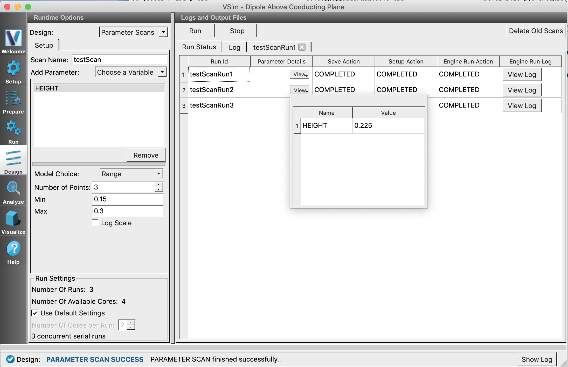
Fig. 110 View Variable and Value
Log Tab: Maintains a log of steps and activities performed in the Parameter Scan Panel.
Running an Analyzer on the Sub Simulation Data
Click on the Analyze icon after the completion of parameter scan. From the Apply To drop down, choose a sub simulation on which the analyzer is to be run. Primary Run refers to the data of the parent simulation. See Fig. 111.
If you want an analyzer to run automatically after each sub simulation engine run, make sure to check Run Automatically After Engine before starting the parameter scan.
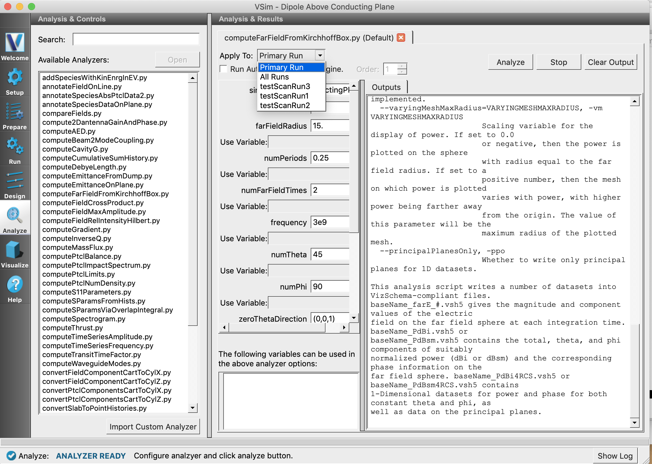
Fig. 111 Analysis of sub simulation data
Visualization of Sub Simulation Data
Click on the Visualize icon on the far left of VSimComposer Window. From the Choose a Run drop down, you will be able to choose the sub simulation whose data you want to visualize. Primary Run refers to the data of the parent simulation. Try Choosing testScanRun1.See Fig. 112.
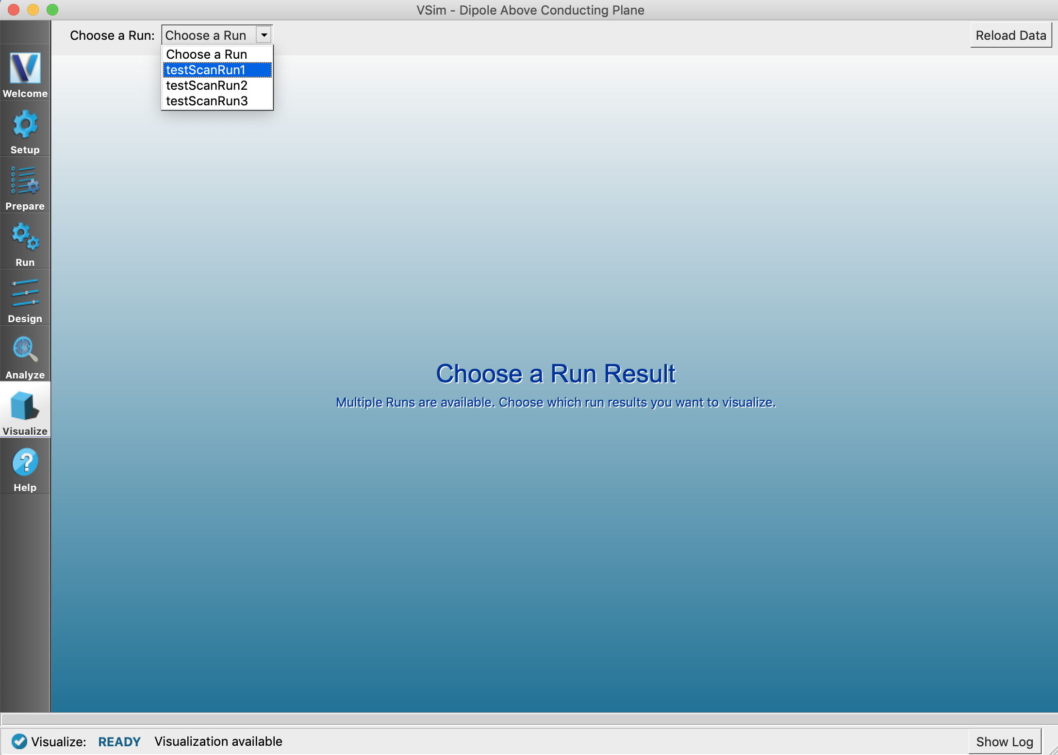
Fig. 112 Choose a sub simulation from the drop down
On the next panel choose Data Overview from the Add a Data View drop down.
The View Parameters button can be clicked to view the variables and their values that was used in the chosen
sub simulation. See vci-param-scan-visualize-a-sub-simulation.
Switching to the visualization of another sub simulation or the parent simulation can be done by choosing desired
option from the Choose a Run drop down.
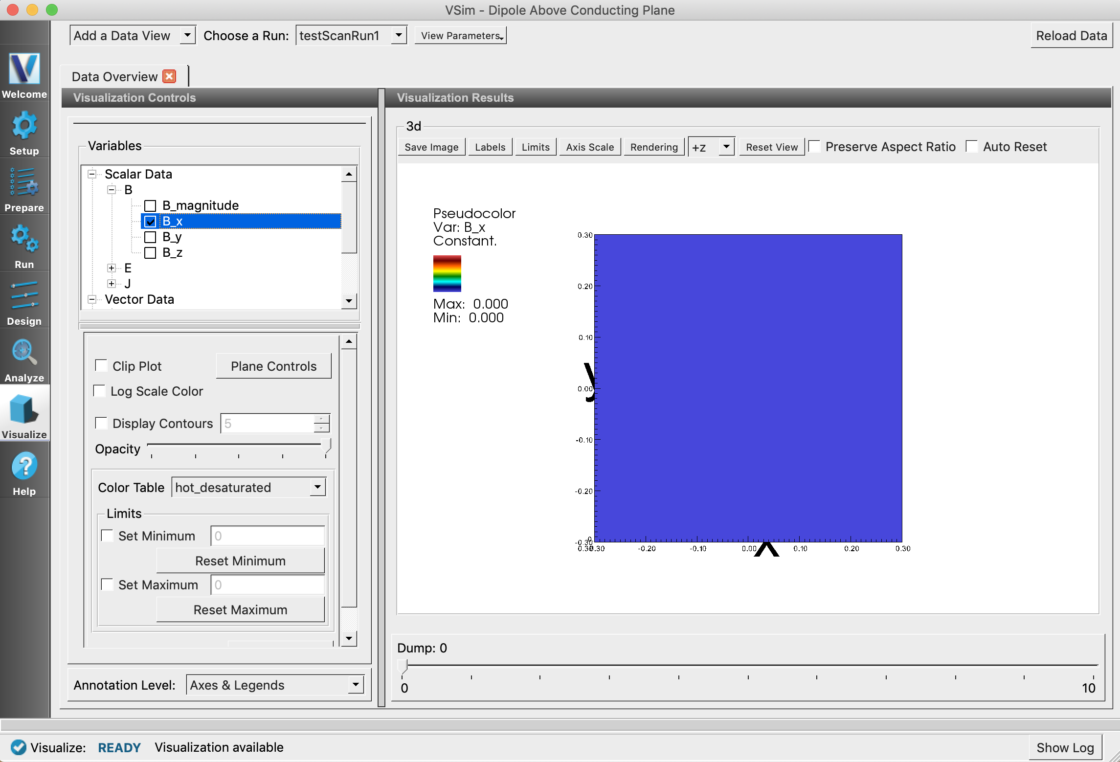
Fig. 113 Visualization of a sub simulation
Directory Structure
First a folder named simulationName_scanName is created in the parent simulation directory. This folder contains individual folders for each sub simulation and a test file named as simulationName_scanNameRunInfo.txt. This file contains all the information (variables used, values, status) about the sub simulations. Folders for each sub simulation contains files and data related to the simulation. The directory structure for our Dipole Above Conducting Plane is shown in Fig. 114 .
Deleting Existing Parameter Scan Data
Clicking Delete Old Scans button, allows deletion of parameter scan files and folders from older runs.
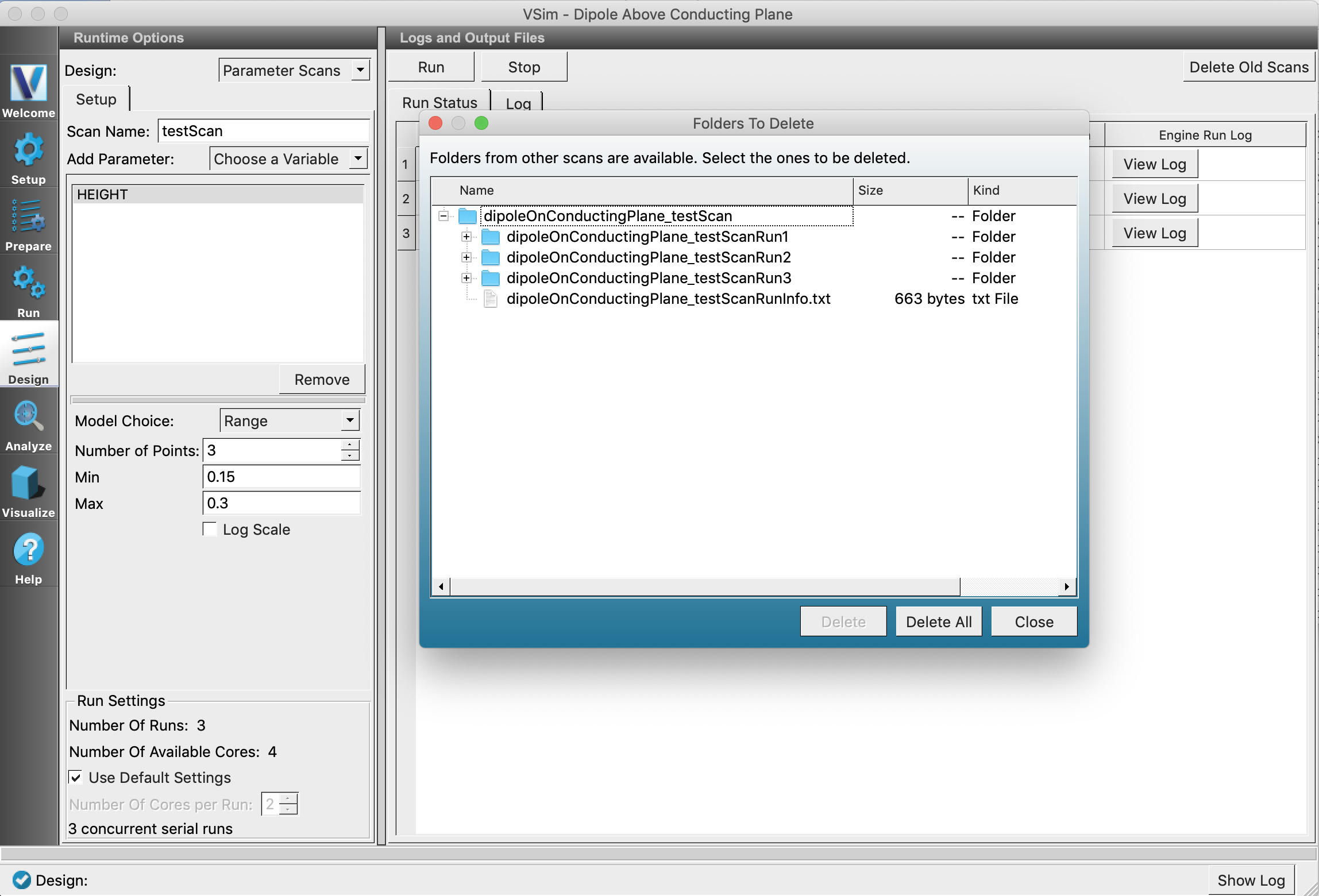
Fig. 114 Delete Old Dialog showing directory structure