Multipacting Growth Using Prescribed Fields (multipactingGrowthPrescribedFields.sdf)
Keywords:
- multipacting
Problem description
Multipacting, which is the resonant buildup of secondary electrons, is often a concern in microwave devices. Anytime there is an oscillating electromagnetic field across a gap between two surfaces there exists the possibility that for the right voltage across the gap a resonance condition will exist allowing the exponential buildup of secondary electrons. This example simulates multipacting growth in a spherical PEC cavity. The fundamental mode profile for the spherical PEC cavity is imported onto the VSim grid, then advanced in time by a single frequency time signal.
This simulation can be performed with the VSimVE or VSimPD license.
Opening the Simulation
The Multipacting Growth Prescribed Fields example is accessed from within VSimComposer by the following actions:
Select the New → From Example… menu item in the File menu.
In the resulting Examples window expand the VSim for Microwave Devices option.
Expand the Multipacting option.
Select “Multipacting Growth Using Prescribed Fields” and press the Choose button.
In the resulting dialog, create a New Folder if desired, and press the Save button to create a copy of this example.
All of the properties and values that create the
simulation are now available in the Setup Window as shown in
Fig. 454. You can
expand the tree elements and navigate through the various
properties, making any changes you desire. The right pane
shows a 3D view of the geometry, if any, as well as the grid,
if actively shown. To show or hide the grid, expand the Grid
element and select or deselect the box next to Grid.
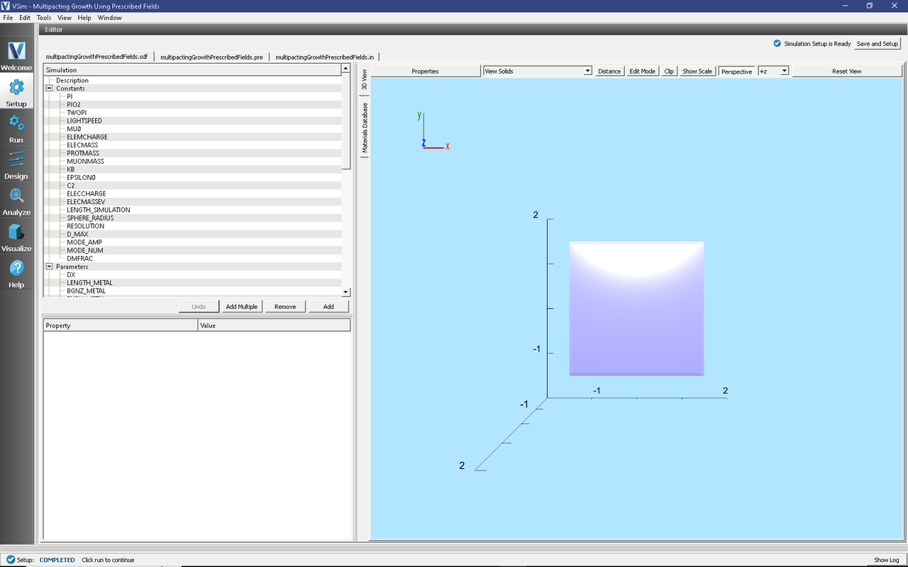
Fig. 454 Setup Window for the Multipacting Growth example.
Simulation Properties
This example contains a number of Constants to allow for easy manipulation of the device. Those include:
SPHERE_RADIUS: radius of spherical cavity
LENGTH_METAL: Length of metal box in each dimension (must be larger than 2*SPHERE_RADIUS)
RESOLUTION: The number of cells per wavelength in each dimension
MODE_NUM: The mode number determining the frequency of field oscillation
SpaceTimeFunctions are used to create expressions defining the drive frequency and amplitude of the applied field.
The amplitude and frequency of this driving function is defined in Parameters:
MODE_FREQ: frequency at which the mode profile oscillates.
MODE_AMP: amplitude that is applied to the mode profile each time step.
CSG is used to create the spherical PEC cavity by subtracting sphere from a cube.
Running the simulation
After performing the above actions, continue as follows:
Proceed to the Run Window by pressing the Run button in the left column of buttons.
To run the file, click on the Run button in the upper left corner. of the window. You will see the output of the run in the right pane. The run has completed when you see the output, “Engine completed successfully.” This is shown in Fig. 455
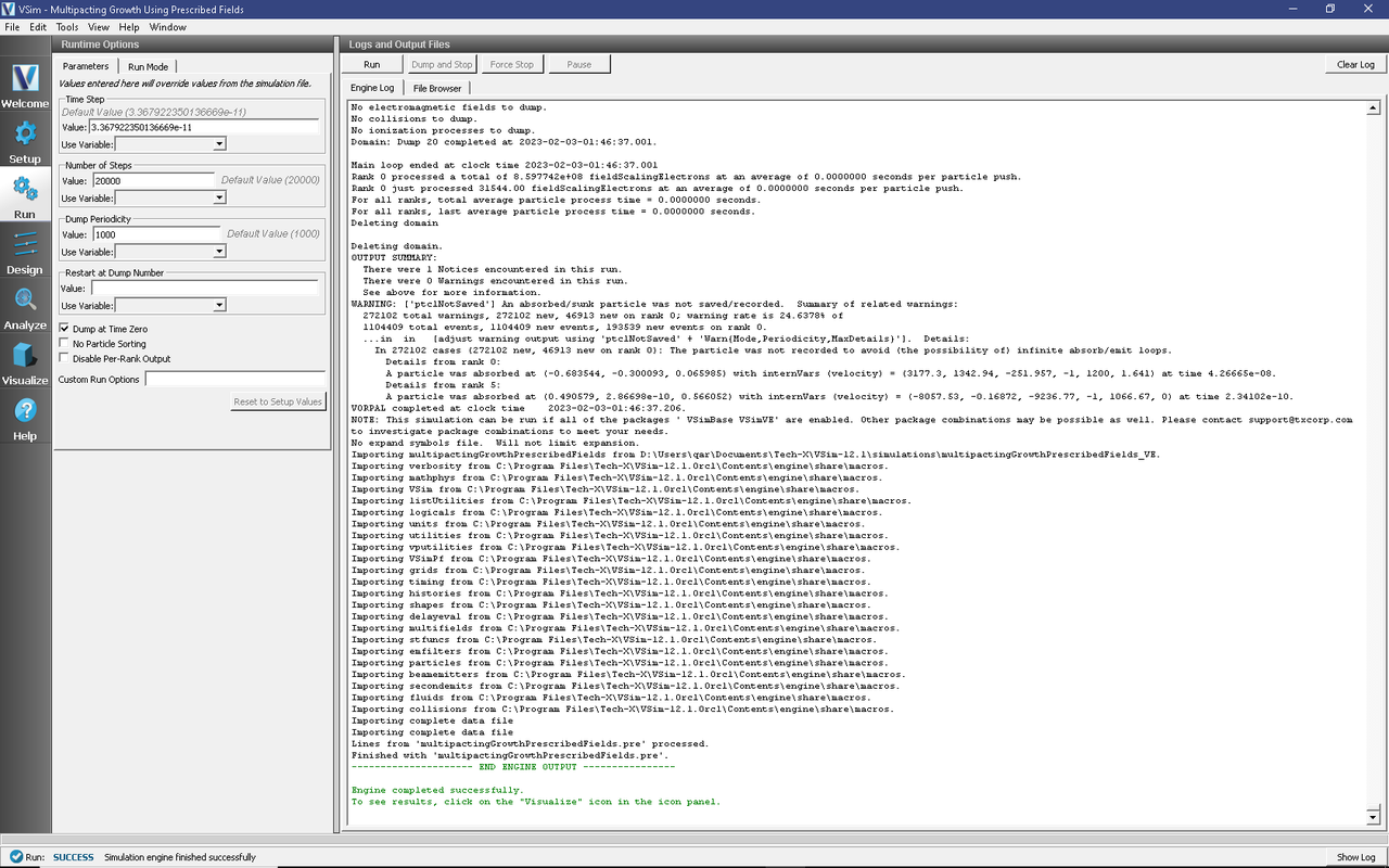
Fig. 455 The Run Window at the end of execution.
Visualizing the results
After performing the above actions, continue as follows:
Proceed to the Visualize Window by pressing the Visualize button in the left column of buttons.
Select Binning from the Data View pull down menu.
Select Auto Reset at the top of the Visualization Window.
To view the field-scaling values at which multipacting occurs, as shown in Fig. 456, use the following settings in Visualization Controls:
Set Dimension 1 → Variable to fieldScalingElectrons_fieldScaledParam.
Set Dimension 1 → Bins to 100 (Note: always set the number of bins to be greater or equal than the number of scaling factors used in the particle setup).
Under Reduction Operator set Operator to Sum and set Variable to fieldScalingElectrons_weight.
Click DRAW.
Move the dump cursor all the way to the right.
The overall trend in the number of electrons is that of an exponential growth with time at the correct field strengths that are controlled by the user’s power settings during the design of the device.
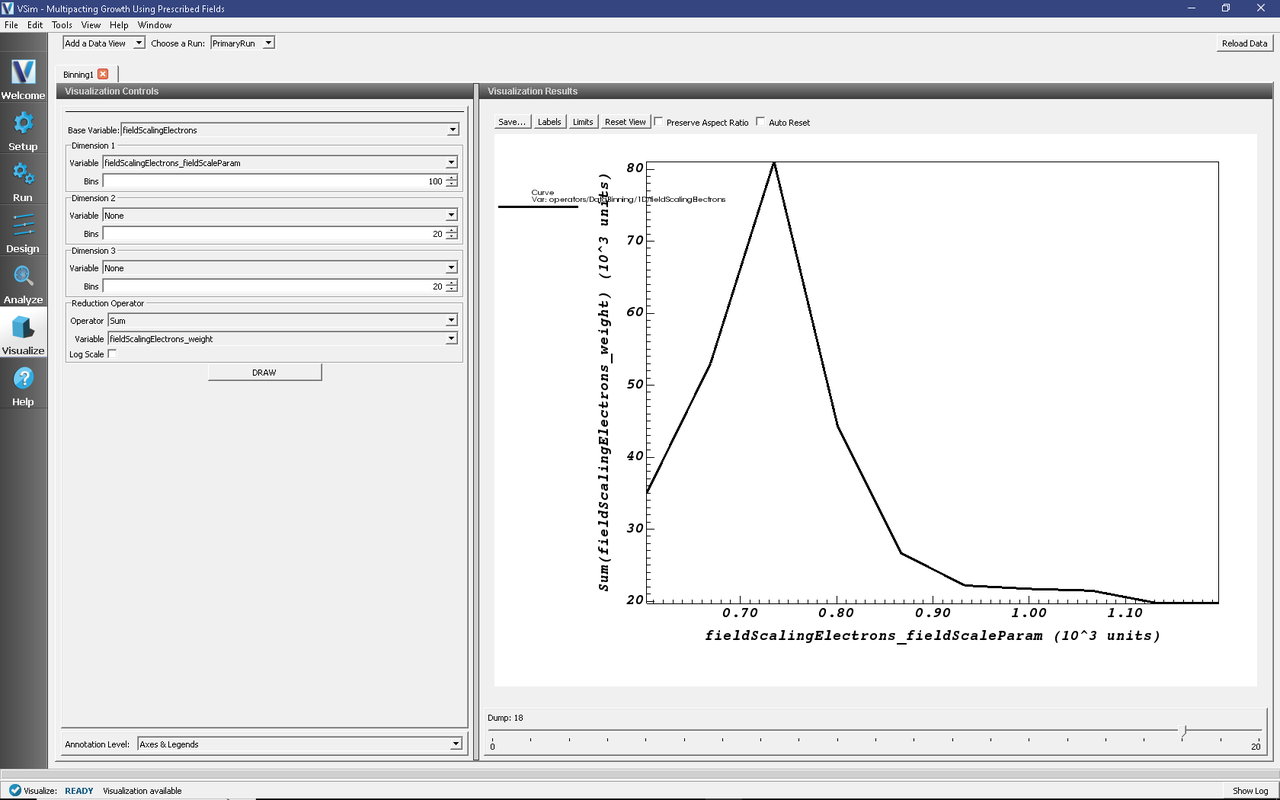
Fig. 456 Visualization of the exponential growth of the electrons due to multipacting.
Further Experiments
Multipacting behavior is sensitive to a number of factors, including the surface material properties, the field strength, and the oscillation frequency. One unmodeled parameter that can greatly affect multipacting is surface roughness. Varying the surface meshing tolerance, set by the DM_FRAC constant in this simulation, can be used as an analogue to tweak the multipacting strength. Try changing the parameters DM_FRAC, MODE_AMP and MODE_NUM to see if one can take the simulation in and out of resonance.