Ion Beam Sputtering (ionBeamSputtering.sdf)
Keywords:
- sputtering, ion beam, electrostatics
Problem Description
In this simulation, a 450 eV beam of positively charged argon ions strikes a copper plate (cathode) at -25 volts with respect to the walls on the upper and lower x boundaries of the simulation. A Neumann boundary condition where the slope of the electric potential is zero is placed on the upper and lower y walls of the simulation.
The argon ion beam travels through a vacuum and sputter off neutral copper atoms from the cathode.
This demonstrates how to set up a sputtering interaction through the Visual Setup in VSimComposer.
This simulation can be performed with a VSimPD license.
Opening the Simulation
The Ion Beam Sputtering example can be accessed from within VSimComposer by the following actions:
Select the New \(\rightarrow\) From Example… menu item in the File menu.
In the resulting Examples window expand the VSim for Plasma Discharges option.
Expand the Sputtering option.
Select “Ion Beam Sputtering” and press the Choose button.
In the resulting dialog, create a New Folder if desired, and press the Save button to create a copy of this example.
You can expand the tree elements and navigate through the various properties, making any changes you desire, but the run here is using the setup as is. The right pane shows a 3D view of the geometry, if any, as well as the grid, if actively shown. The setup window, with the Particle Dynamics \(\rightarrow\) Kinetic Particles \(\rightarrow\) ArgonIons, and neutralCopper elements expanded is shown in Fig. 631.

Fig. 631 Setup window for the Ion Beam Sputtering example.
Simulation Properties
The Ion Beam Sputtering example includes some constants for easy adjustment of simulation properties:
BEAM_RADIUS: sets the radius of the argon ion beam
BEAM_ENERGY: sets the energy (and speed) of the ion beam
BEAM_CURRENT: sets the emitted current. Note: the total current emitted will be less than this value if a mask is applied to the particle emitter (which is the case in this simulation).
CATHODE_VOLTAGE: the negative bias for the cathode.
Running the Simulation
After performing the above actions, continue as follows:
successfully.” This is shown in Fig. 632.

Fig. 632 The Run window at the end of execution.
Visualizing the results
After performing the above actions, continue as follows:
Proceed to the Visualize window by pressing the Visualize button in the left column of buttons. Be sure to press the “Reload Data” button at the bottom of the window if you have previously navigated to the Visualize window.
Expand “Particle Data” then expand “ArgonIons” and check the red “ArgonIons” box.
Expand “neutralCopper” and check the green “neutralCopper” box.
Expand “Scalar Data” and check “Phi”. Then check the “Display Contours” box.
Expand “Geometries” and select poly (cathode).
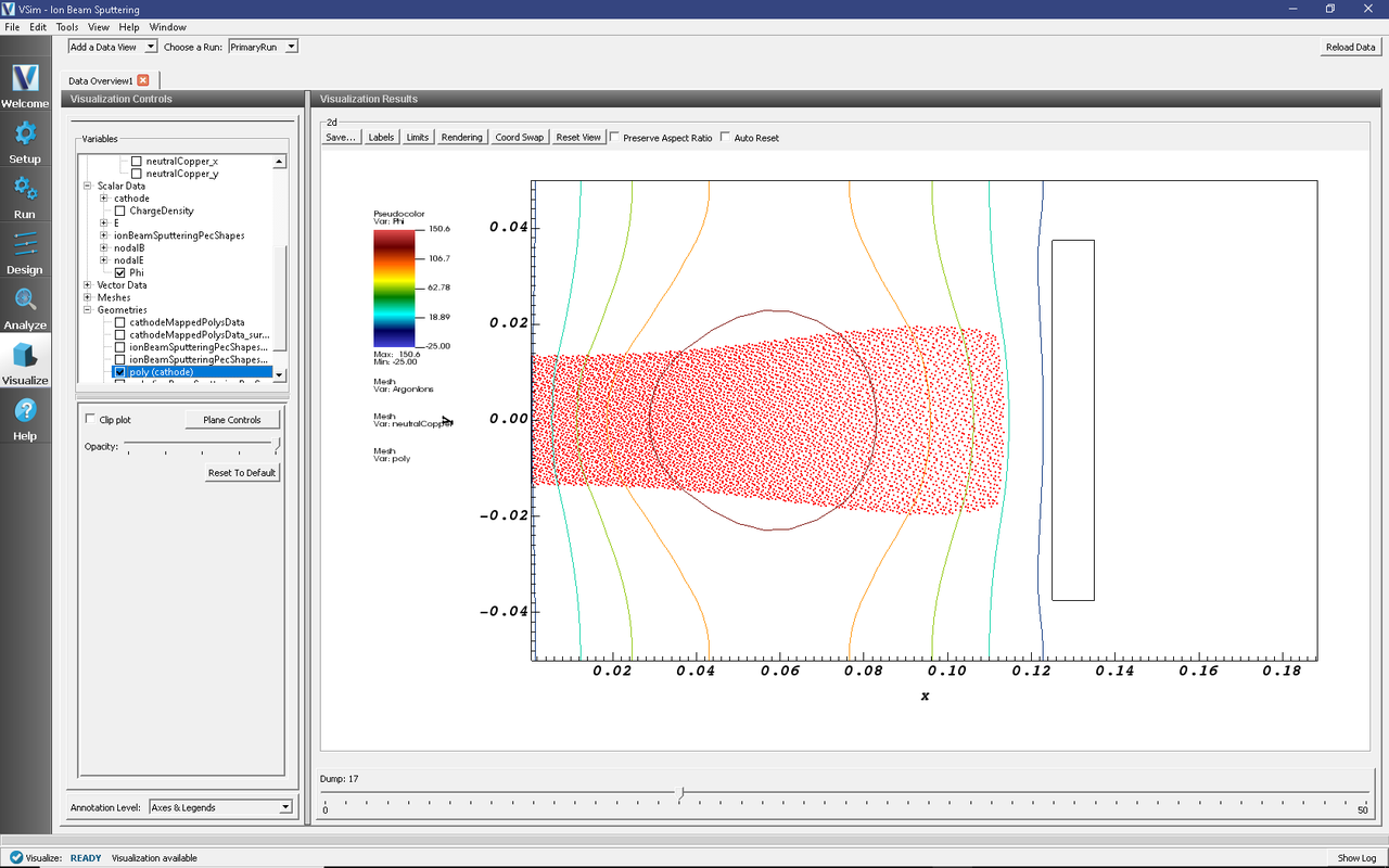
Scrolling through the dumps, you should see the argon beam expand as it travels towards the cathode, as in Fig. 633. Copper atoms will appear after the argon beam strikes the cathode.

Fig. 633 Ion Beam Sputtering an instant before the argon beam strikes the wall.
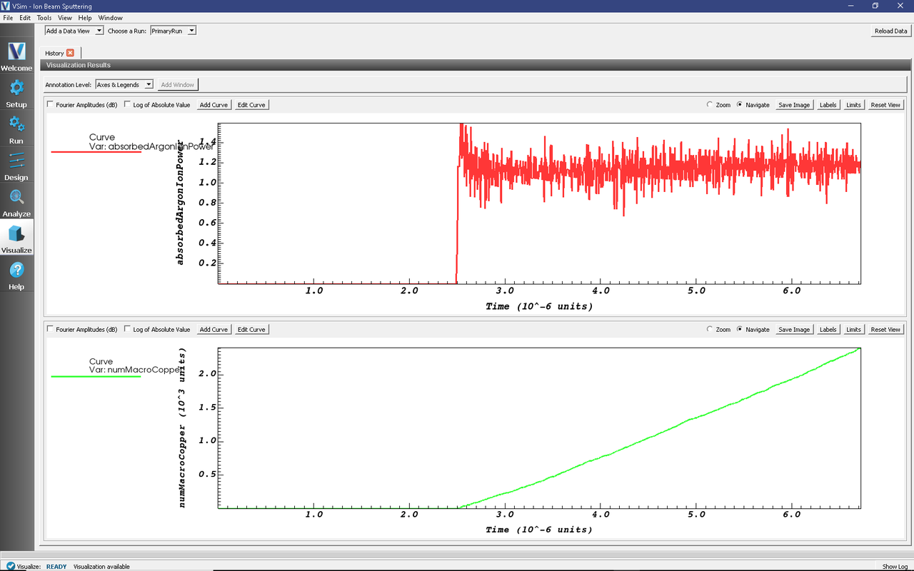
Next, in the Data View drop down menu at the top left of the window, switch from “Data Overview” to “History”. In Graph 2, change from “emittedArgonCurrent” to “<None>” to see the plots shown in Fig. 634

Fig. 634 Plots of the absorbed power and neutralCopper macro particle count.
These plots show the energy deposited onto the cathode from the argon ion species as well as the number of neutral copper macro particles. From these plots its clear that the ion beam strikes the cathode after about 2.5 microseconds. A history for the total number of physical copper atoms is also available to be added to the simulation.
Further Experiments
Vary the BEAM_ENERGY constant, the species of ions in the beam, and the target material to see how the sputter yield changes in response (see the “numMacroCopper” history available in the Visualize Tab).
To change the material of the target to see the effect on the sputtering yield, expand the Particle Dynamics element, then neutralCopper. Select the sputterNeutralEmitter and choose a new material from the “material properties” dropdown menu.
Note
Savvy users may notice that the material of the cathode is also set in the Geometries element under CSG \(\rightarrow\) cathode. This assignment of “PEC” sets the _electromagnetic_ properties of the geometry, not the particle properties.
Add electrons, secondary electron emission, an RF oscillating frequency on the cathode, and possibly an external magnetic field. Add a copperIons species and an electron impact ionization process to create copperIons from neutralCoppers. Add a second copper sputter emitter to the cathode that creates copper neutrals from copperIons to simulate self-sputtering.
Modify the beam current to account for the loss in current due to the mask. See the Negative Ion Beam example (Negative Ion Beam (negativeIonBeam.sdf)) for an example of how this is accomplished.