Ground Penetrating Radar (groundPenetratingRadarT.pre)
Keywords:
- GPR, ground penetrating radar, lossy dielectric
Problem description
This simulation launches a plane wave, polarized in the Z-direction into a lossy dielectric. Embedded within the lossy dielectric is a mine, modelled as a pure electric conductor. The return wave at the surface can be monitored with histories. The simulation is 2D, but with minor effort can be expanded to 3 dimensions.
This simulation can be performed with a VSimEM license.
Opening the Simulation
The Ground Penetrating Radar example is accessed from within VSimComposer by the following actions:
Select the New → From Example… menu item in the File menu.
In the resulting Examples window expand the VSim for Electromagnetics option.
Expand the Scattering (text-based setup) option.
Select “Ground Penetrating Radar (text-based setup)” and press the Choose button.
In the resulting dialog, create a New Folder if desired, and press the Save button to create a copy of this example.
The key parameters of this problem should now be alterable via the text boxes in the left pane of the Setup Window, as shown in Fig. 324.
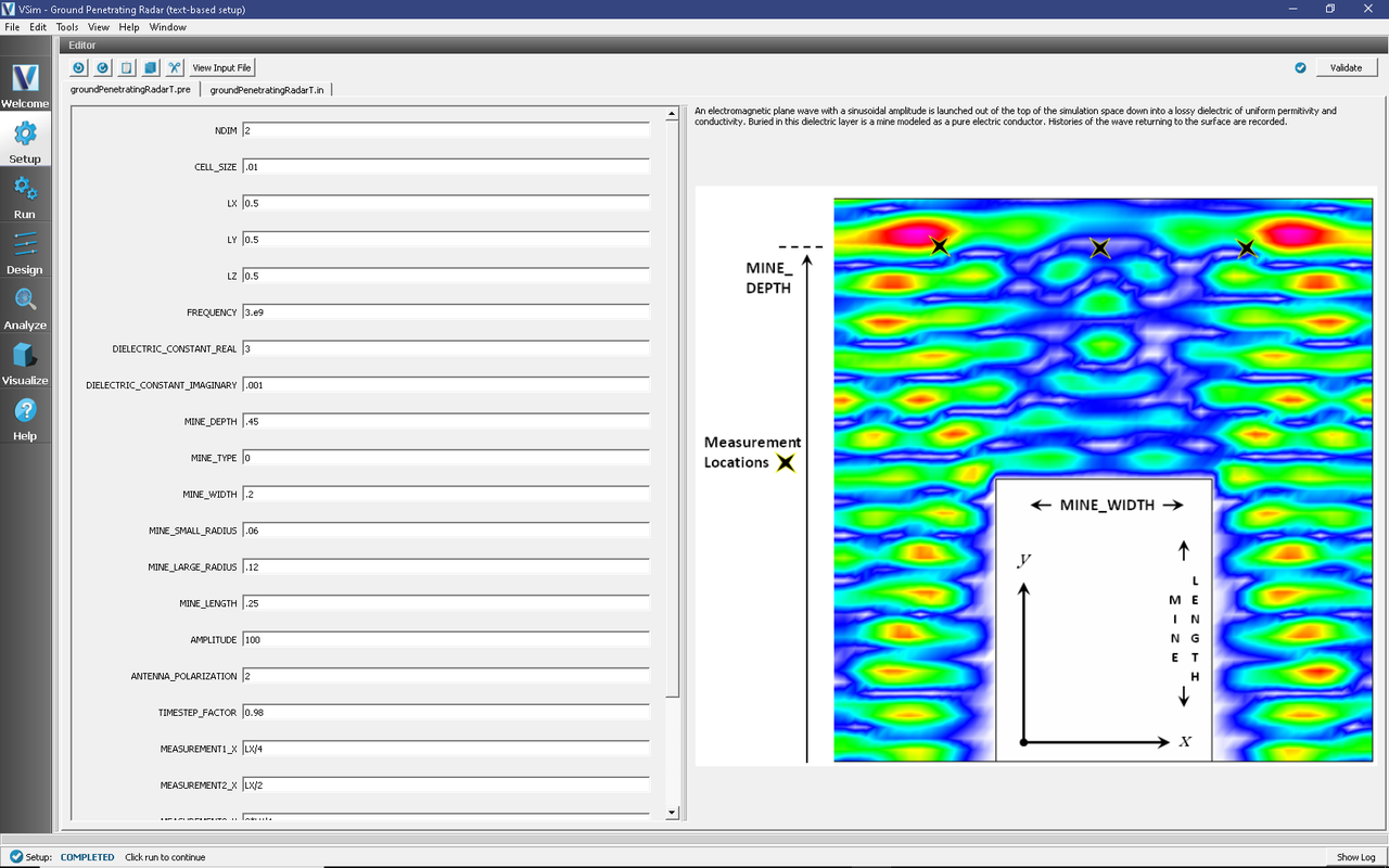
Fig. 324 Setup Window for the Ground Penetrating Radar example.
Input File Features
This file allows for the modification of plane wave operating frequency, simulation domain size, resolution, dielectric permittivity, size and conductivity, mine size and location as well as history location.
Running the Simulation
After performing the above actions, continue as follows:
Proceed to the Run Window by pressing the Run button in the left column of buttons.
To run the file, click on the Run button in the upper left corner of the window. You will see the output of the run in the right pane. The run has completed when you see the output, “Engine completed successfully.” This is shown in the window below.
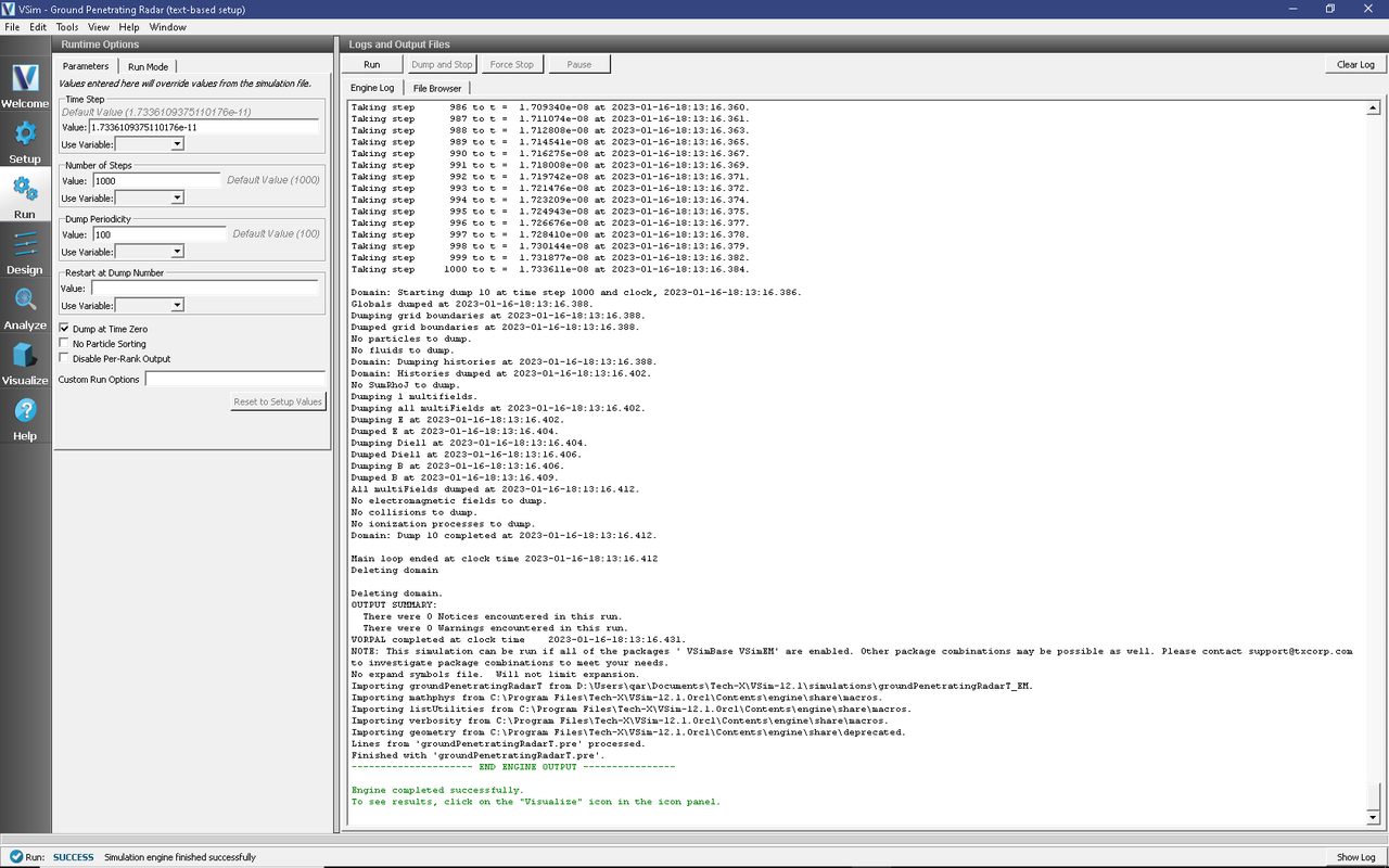
Fig. 325 The Run Window at the end of execution.
Visualizing the Results
After the simulation has completed running, click on the Visualize Window.
The electric field can be viewed by:
Expand Scalar Data
Expand E
Select E_z
Expand Geometries
Select poly
Move the dump slider forward in time
The wave reflection measured at the three surface locations can be viewed under the Histories Data View
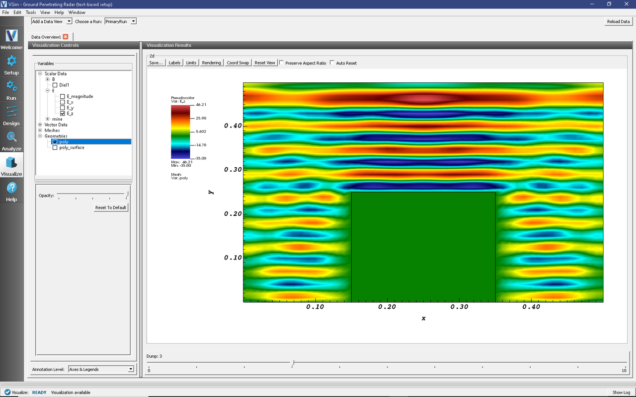
Fig. 326 The electric field in the simulation space. Seen here: the cylindrical cone mine-shape.
Further Experiments
The parameters of the dielectric can be easily modified. It would also be possible to modify the sources to be horn antennas instead of point sources; this would more accurately model a real world ground penetrating radar situation.