Photonic Crystal in Metal Cavity (phcInMetalCavityT.pre)
Problem Description
A photonic crystal (PhC) is capable of confining electromagnetic fields in waveguides and cavities using a periodic geometry. This simulation features a dielectric photonic crystal cavity—a triangular lattice of dielectric rods, with one rod removed—inside a metal cavity. The cavity axis, and the dielectric rods, are in the \(z\) direction.
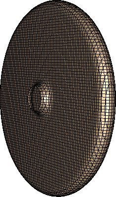
Fig. 333 The metal cavity surrounding the PhC structure.
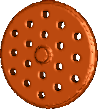
Fig. 334 The vacuum region (inside the metal cavity, outside the dielectric rods).
The photonic crystal structure is similar to that described in [BWC08], truncated after two layers of the lattice structure. The metal cavity resembles an elliptical (or rounded pillbox) cavity, with short beam tubes.
Modeling dielectric and metal can be difficult: at dielectric corners or triple points (where dielectric, metal, and vacuum meet), the electromagnetic fields generally must diverge (to infinity) to preserve continuity dictated by Maxwell’s equations [Had02]. However, when the interface between dielectric and vacuum is always perpendicular to the metal surface, as in this simulation, the fields remain finite.
This simulation demonstrates a method for combining dielectric and metal, as long as the metal surface is perpendicular to \(x\), \(y\), or \(z\) whenever it intersects dielectric (and the vacuum/dielectric interface remains perpendicular to the metal surface at those points).
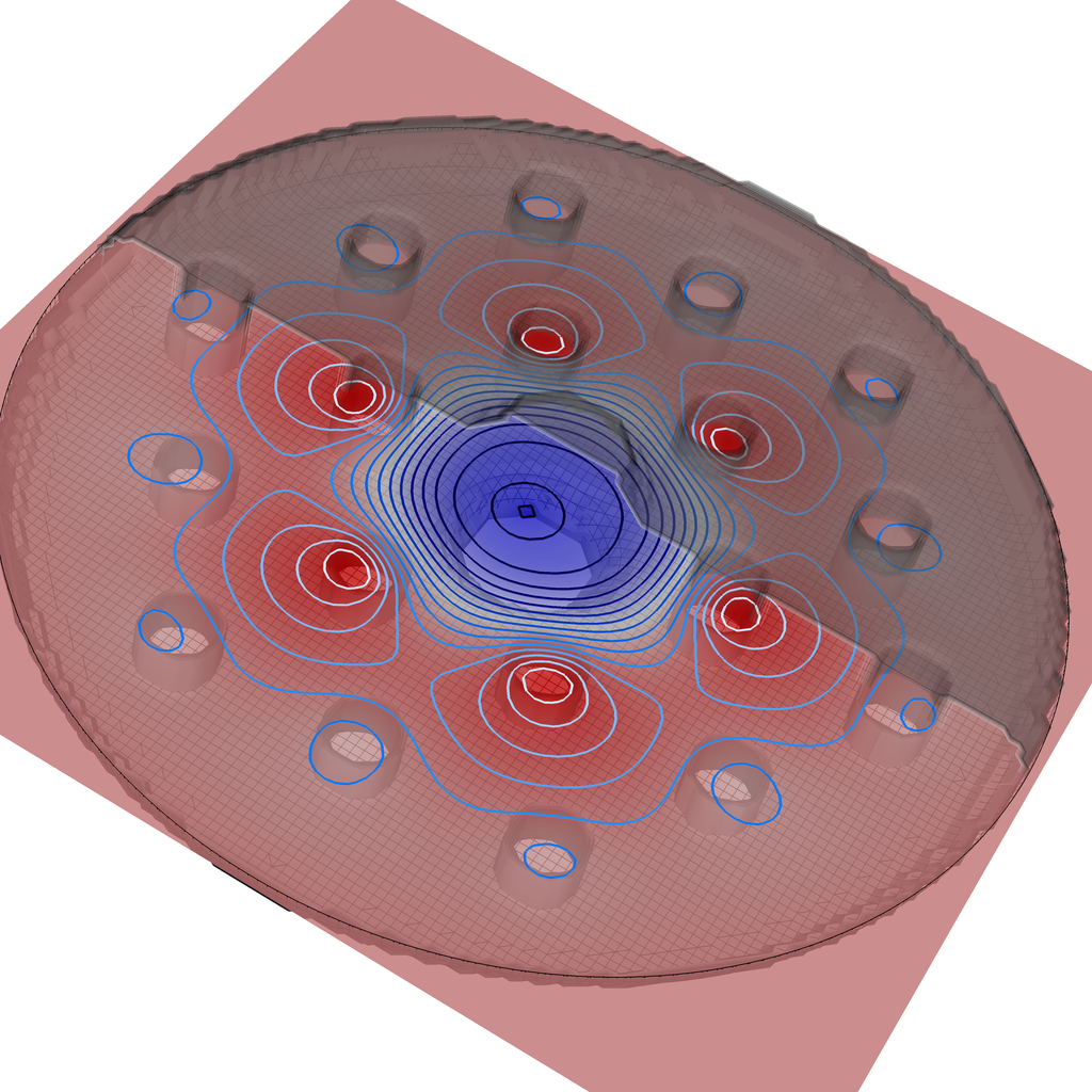
When the PhC cavity mode is excited, the fields are trapped radially mainly by the dielectric rods.
This simulation can be performed with a VSimEM, VSimVE or VSimPA license.
Opening the Simulation
The PhC in Metal Cavity example is accessed from within VSimComposer by the following actions
Select the New → From Example… menu item in the File menu.
In the resulting Examples window expand the VSim for Electromagnetics option.
Expand the Other EM (text-based setup) option.
Select “Photonic Crystal in Metal Cavity (text-based setup)” and press the Choose button.
In the resulting dialog, create a new folder if desired, and press the Save button to create a copy of this example.
The basic variables of this problem will now be alterable via the text boxes in the left pane of the Setup Window, as shown in Fig. 335.
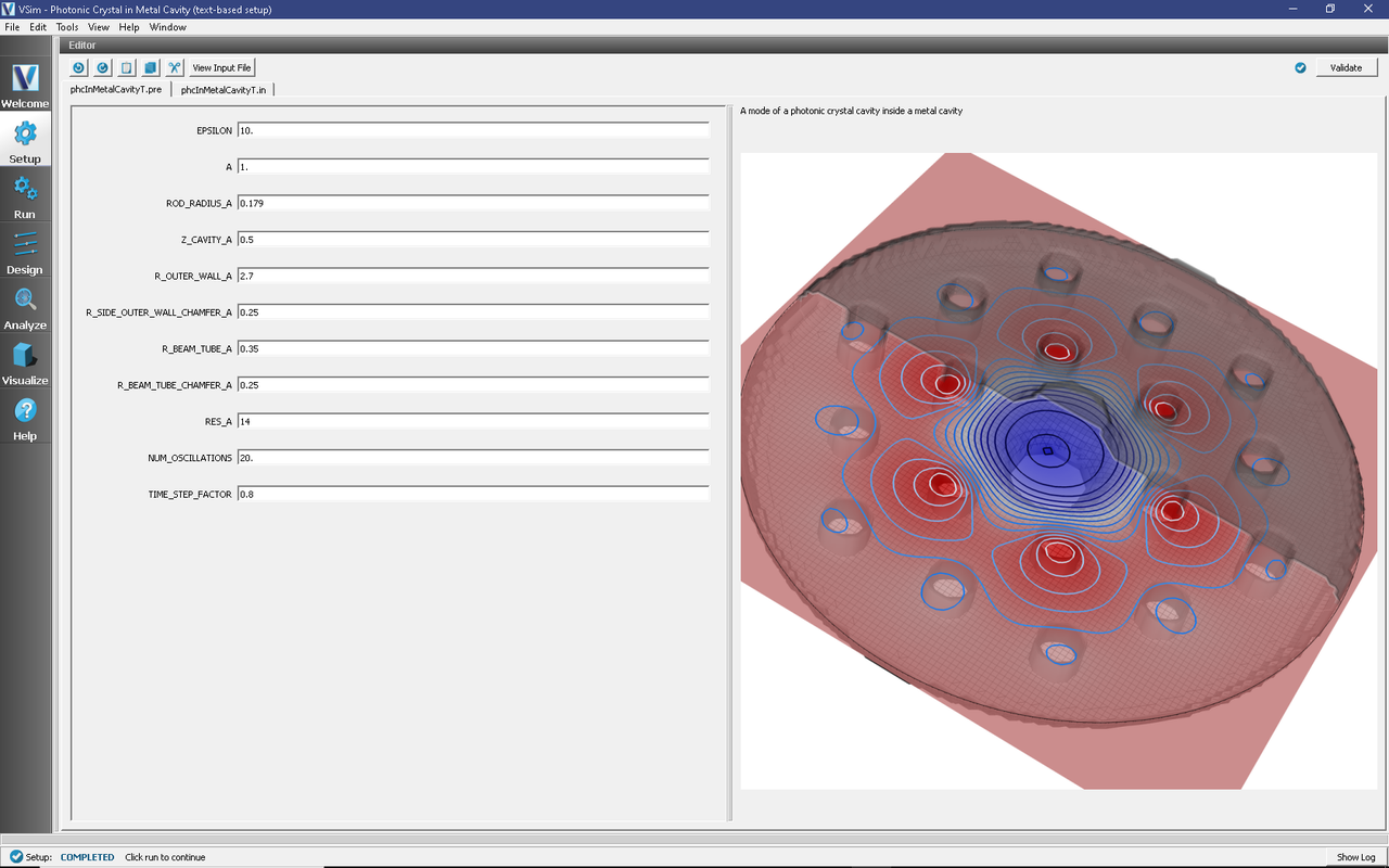
Fig. 335 Setup Window for the phcInMetalCavityT example.
Input File Features
The input file allows the user to choose the dielectric contrast and radius of the rods, the shapes and sizes of the cavity and beam tubes (to some extent), the grid resolution, and the number of oscillations to simulate after excitation. The entire simulation is scaled to the lattice constant, which is set to 1 by default.
Running the simulation
After performing the above actions, continue as follows:
Proceed to the Run Window by pressing the Run button in the left column of buttons.
To run the file, click on the Run button in the upper left corner of the right pane of the window. You will see the output of the run in that pane. The run has completed when you see the output “Engine completed successfully.” This is shown in Fig. 336.
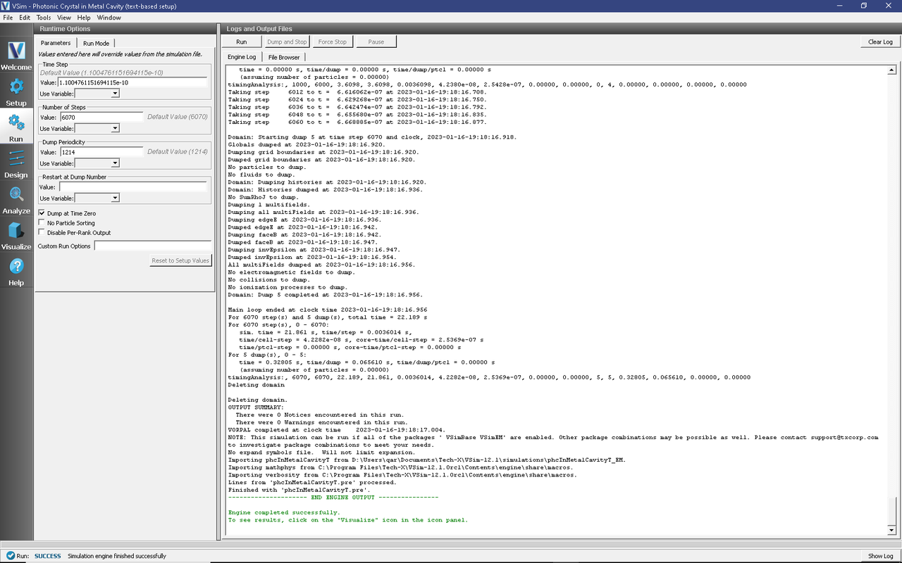
Fig. 336 The Run Window at the end of execution.
Visualizing the results
After performing the above actions, continue as follows:
Proceed to the Visualize Window by pressing the Visualize button in the left column of buttons.
Due to the symmetry of this system, the results are best viewed by looking at the \(z\) component of the electric field as follows:
Expand Scalar Data
Expand edgeE
Select edgeE_z and check the box next to Clip Plot
Expand Geometries
Select poly and check the box next to Clip Plot again
The field at dump 2 is shown in Fig. 337.
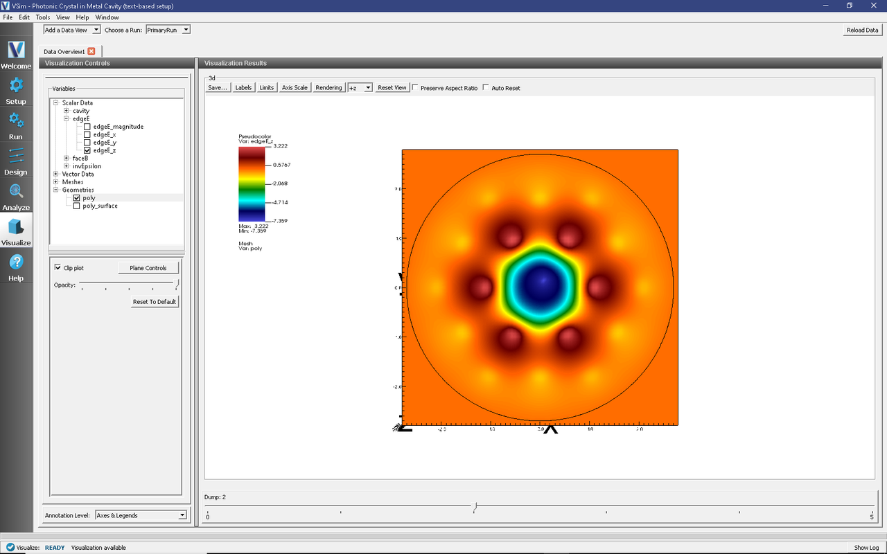
Fig. 337 Visualization of the \(E_z\) field component.
We can see that fields are trapped by the two layers of dielectric rods, and to a lesser (but final) extent by the surrounding metal cavity.