Geometries
The Geometries element contains information about any geometries that are in the simulation. You can import from several types of CAD files, or create your own with CSG using the primitive shapes described below.
Be sure to assign a Material to a geometry object before it will appear elsewhere in the simulation (i.e. as an option for a particle source or tally). Materials can also be assigned to all geometries with a .csv file. See Material Annotation for further details.
If a geometry is unchecked, it will be hidden from view and removed from the simulation.
All geometries can be assigned a color, either directly or based on the material. See Color Assignment for further details of color assignment.
CSG
Constructive Solid Geometry can be used to build your own complex geometry.
- kind (not editable)
- Construction Group
- relative tessellation
Only applied if Constructive Solid Geometry format in Basic Settings is set to tessellated.
Relative tessellation is used to calculate the absolute tessellation which is seen under each solid. Tessellation, also known as linear deflection, represents the upper limit of the distance between a curve and a side of a triangle. This is required to control the fineness of surface meshes of CSG objects. If the dimensions of shapes we are working on were known in advance and were always the same, we could use a constant value of tessellation. But that is not the case. for example, a tessellation of 0.01mm for a 1mm sphere would produce fewer triangles than the same tessellation for 1m sphere. So, in order to have proportional number of triangles, we need to scale the relative tessellation with some scale factor. The value calculated in that manner is called tesellation and is actually applied to the CSG objects. This is the value that appears under each solid.
tessellation = relative tessellation * diagonal length of bounding box of the shape.
Users do not have to worry about the tessellation as it is taken care by RSim. To change the fineness, they can simply change the relative tessellation value in the GUI and actual tessellation is calculated under the hood.
The relative tessellation or the GUI tessellation is the standard that we use. Roughly for every shape of dimension 1m, a tessellation of approximately 0.001m is reccomended.
Sphere
- kind (not editable)
- Sphere
- material
- The material to use for the shape. Chosen from a list of imported materials in your simulation.
- radius
- The radius of the sphere.
- x position
- The location of the center of the sphere in the x direction.
- y position
- The location of the center of the sphere in the y direction.
- z position
- The location of the center of the sphere in the z direction.
Box
- kind (not editable)
- Box
- material
- The material to use for the shape. Chosen from a list of imported materials in your simulation.
- length
- The length of the box.
- height
- The height of the box.
- width
- The width of the box.
- x position
- The location of the center of the box base in the x direction.
- y position
- The location of the center of the box base in the y direction.
- z position
- The location of the center of the box base in the z direction.
- width direction x
- Set to 1 to make the width parameter of the box correspond to the x direction.
- width direction y
- Set to 1 to make the width parameter of the box correspond to the y direction.
- width direction z
- Set to 1 to make the width parameter of the box correspond to the z direction.
- angle
- The angle of the box.
Cylinder
- kind (not editable)
- Cylinder
- material
- The material to use for the shape. Chosen from a list of imported materials in your simulation.
- length
- The length of the cylinder.
- radius
- The radius of the cylinder.
- x position
- The location of the base of the cylinder in the x direction.
- y position
- The location of the base of the cylinder in the y direction.
- z position
- The location of the base of the cylinder in the z direction.
- axis direction x
- Set to 1 to make the axial direction of the cylinder x; if set to -1, the length parameter will extend in the negative direction.
- axis direction y
- Set to 1 to make the axial direction of the cylinder y; if set to -1, the length parameter will extend in the negative direction.
- axis direction z
- Set to 1 to make the axial direction of the cylinder z; if set to -1, the length parameter will extend in the negative direction.
Cone
- kind (not editable)
- Cone
- material
- The material to use for the shape. Chosen from a list of imported materials in your simulation.
- height
- The height of the cone.
- radius
- The radius of the base of the cone.
- x position
- The location of the center of the cone base in the x direction.
- y position
- The location of the center of the cone base in the y direction.
- z position
- The location of the center of the cone base in the z direction.
- axis direction x
- Set to 1 to make the axial direction of the cone x.
- axis direction y
- Set to 1 to make the axial direction of the cone y.
- axis direction z
- Set to 1 to make the axial direction of the cone z.
Torus
- kind (not editable)
- Torus
- material
- The material to use for the shape. Chosen from a list of imported materials in your simulation.
- major radius
- The radius to the center of the torus.
- minor radius
- The radius from the center of the torus to the outside of the torus.
- x position
- The location of the center of the torus in the x direction.
- y position
- The location of the center of the torus in the y direction.
- z position
- The location of the center of the torus in the z direction.
- axis direction x
- Set to 1 to make the axial direction of the torus x.
- axis direction y
- Set to 1 to make the axial direction of the torus y.
- axis direction z
- Set to 1 to make the axial direction of the torus z.
Pipe
- kind (not editable)
- Pipe
- material
- The material to use for the shape. Chosen from a list of imported materials in your simulation.
- length
- The length of the pipe.
- inner radius
- The inner radius of the pipe.
- outer radius
- The outer radius of the pipe.
- x position
- The location of the base of the pipe in the x direction.
- y position
- The location of the base of the pipe in the y direction.
- z position
- The location of the base of the pipe in the z direction.
- axis direction x
- Set to 1 to make the axial direction of the pipe x; if set to -1, the length parameter will extend in the negative direction.
- axis direction y
- Set to 1 to make the axial direction of the pipe y; if set to -1, the length parameter will extend in the negative direction.
- axis direction z
- Set to 1 to make the axial direction of the pipe z; if set to -1, the length parameter will extend in the negative direction.
TruncCone
- kind (not editable)
- TruncCone (Truncated Cone)
- material
- The material to use for the shape. Chosen from a list of imported materials in your simulation.
- height
- The height of the cone.
- radius1
- The radius of the base of the cone.
- radius2
- The radius of the top of the cone.
- x position
- The location of the center of the cone base in the x direction.
- y position
- The location of the center of the cone base in the y direction.
- z position
- The location of the center of the cone base in the z direction.
- axis direction x
- Set to 1 to make the axial direction of the cone x.
- axis direction y
- Set to 1 to make the axial direction of the cone y.
- axis direction z
- Set to 1 to make the axial direction of the cone z.
Wedge
- kind (not editable)
- Wedge
- material
- The material to use for the shape. Any material in the Materials tab is available for use materials in your simulation.
- length1
- One length of the wedge.
- length2
- The second length of the wedge.
- height
- The height of the wedge.
- width
- The width of the wedge. Extrudes the wedge from a two dimensional to three dimensional object.
- x position
- The location of the base of the wedge in the x direction.
- y position
- The location of the base of the wedge in the y direction.
- z position
- The location of the base of the wedge in the z direction.
- width direction x
- Set to 1 to apply the width parameter in the x direction.
- width direction y
- Set to 1 to apply the width parameter in the y direction.
- width direction z
- Set to 1 to apply the width parameter in the z direction.
Ellispsoid
- kind (not editable)
- Wedge
- material
- The material to use for the shape. Any material in the Materials tab is available for use materials in your simulation.
- radius 1
- The radius of the ellipsoid in the x direction.
- radius 2
- The radius of the ellipsoid in the y direction.
- radius 3
- The radius of the ellipsoid in the z direction.
- x position
- The location of the center of the ellipsoid in the x direction.
- y position
- The location of the center of the ellipsoid in the y direction.
- z position
- The location of the center of the ellipsoid in the z direction.
- Longest Principal Axis Direction X
- Can be used to set the angle of the ellipsoid.
- Longest Principal Axis Direction Y
- Can be used to set the angle of the ellipsoid.
- Longest Principal Axis Direction Z
- Can be used to set the angle of the ellipsoid.
Boolean Operations
CSG primitives and CAD objects may be combined into new geometries in three different ways:
- Subtract
- This will subtract the second selected object from the first selected object. Denoted by \(-\).
- Union
- This will combine the two objects into a single object. Denoted by \(\cup\).
- Intersect
- This will leave only the volume of the two objects that intersect as an object. Denoted by \(\cap\).
It is possible to combine two CSG primitives, two CAD objects, or CSG and CAD objects.
Boolean operations may be nested, for example two objects may be combined in a union, and then with a third oobject in a second union. To combine objects, you must first add two or more shapes to your simulation. Once the shapes are in the simulation, highlight the two shapes you wish to combine and right-click and select Boolean Operation then the operation you wish to perform. The combined object must then be assigned a material, and the parts of the combined object can no longer be assigned a material or used in the simulation.
Arrays
CSG objects, CAD objects, as well as booleaned objects may have a cubic array created from the initial shape. This is particularly useful for repeated structures.
An array is specified with
- X Count
- Number of elements in the X direction.
- X Spacing
- Spacing between the origin of elements in the X direction. The origin will depend on the element being arrayed, for example spheres will be the center of the sphere, while cylinders will be the center base of the cylinder.
- Y Count
- Number of elements in the Y direction.
- Y Spacing
- Spacing between the origin of elements in the Y direction.
- Z Count
- Number of elements in the Z direction.
- Z Spacing
- Spacing between the origin of elements in the Z direction.
It is also possible to array all elements of the array after creation by checking the Union Created Shapes box.
Upon creation the array will propagate outward in the positive X/Y/Z directions. After creation each individual array element can be moved like any other object.
CAD
You can import .stl, .stp or .step, .ply, .vtk, files by right-clicking the Geometries element and selecting Import Geometries. These imported files will appear under the CAD Object.
The relative tessellation of these files can be set prior to importing them. It works similar to the CSG relative tessellation explained in CSG section above. It is recommended to do this with large and complex files, as the tessellation process can take some time.
These imported files will maintain any hierarchical structure within them.
CAD File Healing
It is common for CAD files from differing sources to have minor issues that may impact the accuracy or ability to run a smulation.Most commonly a file can have a tiny hole, caused by a missing triangle in the mesh from when it was originally exported. Any stl file in RSim2 can be analyzed for these problems, and automatically repaired. This is done by right clicking on the CAD file, which will bring up a menu as shown below.
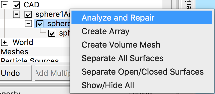
The Analyze and Repair option will bring up a menu to analyze the file, and will report on the number of closed surfaces, open surfaces, loops and holes.
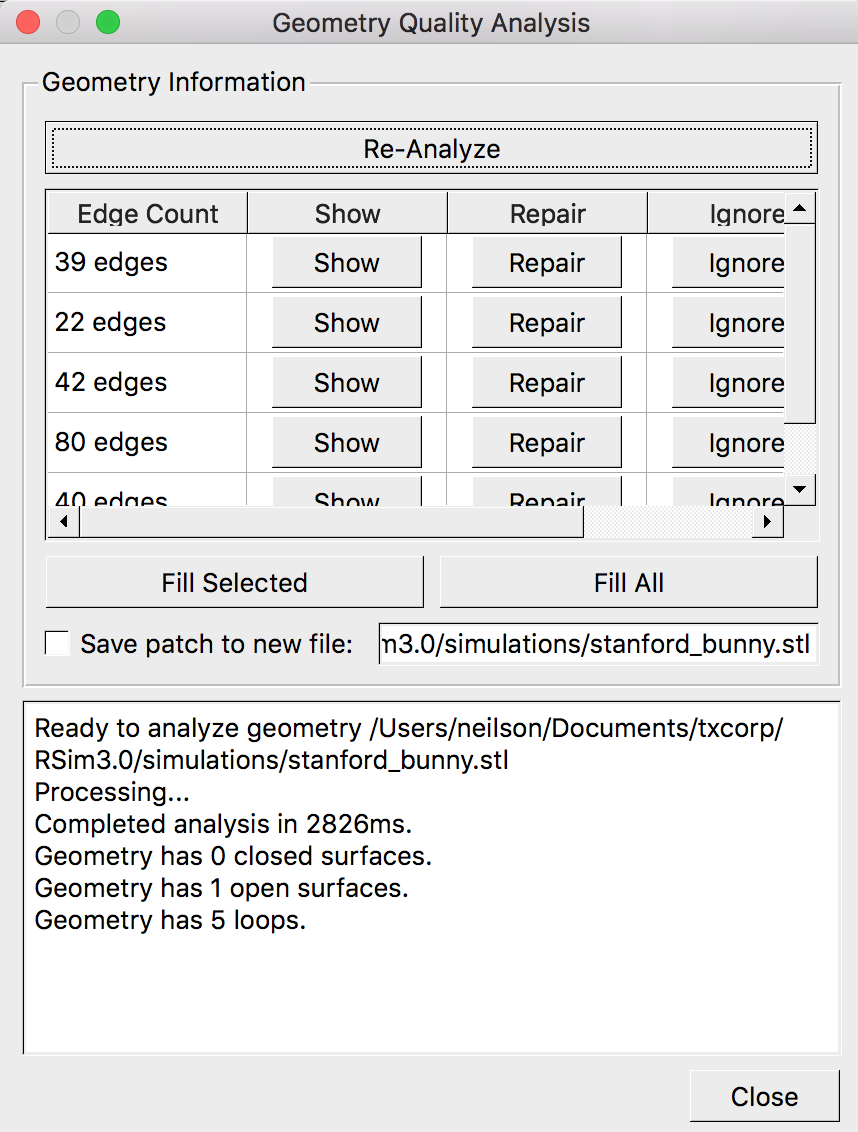
Clicking Show will show each individual hole, Repair will repair that hole, and Ignore will remove it from consideration. Selecting Fill Selected will fill the selected holes, while Fill All will fill every hole listed.
Separate All Surfaces will create new files for each distinct surface in the file. These files will be listed in the tree and can be given a material or assigned to a tally like any other.
Separate Open/Closed Surfaces will create a new file for the closed surfaces. These files will be listed in the tree and can be given a material or assigned to a tally like any other.
Imported
You can import a geometry of type .gdml (tessellated only), .h5m, .ele/.node, or .p12 by right-clicking the Geometries element and selecting Import Geometries.
Imported files of these types do not require tessellation, as they already will have been and be used at their native resolution.
kind (not editable)
- TriangSolid
- OceStepFromFile
- filename
- The name and location of the imported file.
- groupname
- The group name of the file, if relevant.
- verboseRead (not editable)
- Set to 0.
- scale
- A factor to scale the imported geometry by.
- x-translation
- The entire imported geometry will be moved in the x-direction by this amount.
- y-translation
- The entire imported geometry will be moved in the y-direction by this amount.
- z-translation
- The entire imported geometry will be moved in the z-direction by this amount.
World
The World object is always present, and will set the outer bounds of the simulation.
The World is always centered around (0,0,0) and allows for specification of the total X, Y and Z length.
Using GDML files in Geant4 C++ Applications
If one wants to use RSim only for creating complex geometries and develop their own Geant4-based C++ applications, should have this in their detector construction class:
#include "G4GDMLParser.hh"
#include "G4VPhysicalVolume.hh"
#include "G4RunManager.hh"

// In constructor

G4GDMLParser* parser = new G4GDMLParser();
parser->Read(gdmlFile); // gdmlFile is G4String with the name of the file.
fWorld = parser->GetWorldVolume(); //Now you have all world with all volumes in it
G4RunManager::GetRunManager()->DefineWorldVolume(fWorld);
G4RunManager::GetRunManager()->GeometryDirectlyUpdated();