Electric and Magnetic Fields
The electric and magnetic fields are the most important fields in XSim, as they impact the motion of charged particles. In this section we discuss how fields generally work, then we discuss the field update concept. We then discuss the particulars of the updates for each of electromagnetics and electrostatics.
Field Basics
The general concept of a field is a scalar, vector, or tensor
that is a function of space and time. It is most commonly
implemented in XSim by values on a grid, i.e, a value for each
cell. For finite difference methods, the different components
(e.g., vector components) have a location, i.e., place where they
most accurately represent the field value, within each cell. For
a scalar field, like the electrostatic potential, the location is
either at the node (lower corner) or the cell center. For a
vector field, the natural locations are either at the centers of
the edges or at the centers of the faces. Hence, a field in XSim
has a property, offset, that determines this offset.
Fields can be messaged as needed and described in Parallelism and Decomposition. In XSim, fields are messaged according to their overlap, and they are always messaged both up and down.
Some fields are used for deposition of charge and/or current. These deposition fields come with a few changes. First, they are automatically zeroed at the beginning of each time step. Second, to get the charge and current correct in a parallel simulation, the contributions in the guard cells on one domain have to be sent to the owning domain and be added into the charge or current on that domain.
Field Updating Basics
Fields can be either static or dynamic. E.g., the magnetic field in an electrostatic simulation does not evolve. It is set once, and that field is used throughout the simulation. On the other hand, the electric field in an electromagnetic or electrostatic simulation changes at each time step, and the magnetic field in an electromagnetic simulation also changes at each time step. In addition, a field may be made up of a static part and a dynamic part, in which case the two are added together to get the total field at each time step.
The update of a field can be either explicit or implicit. Explicit means that one can write the new field at a given cell in terms of the old field values. Implicit means that one must solve an equation for the new field values. An example of the latter, to be discussed in more detail. In either case, one is updating the field, and the object that does this is known as an updater.
Electromagnetics
In electromagnetic simulations the electric and magnetic fields obey Maxwell’s equations, i.e., Ampere,
and Faraday.
These are discretized and updated using the Yee algorithm
[Yee66]. In that algorithm staggered grids are
used, which is equivalent to saying that the electric field is an
edge field, and the magnetic field is a face field, following
Grids. The Yee algorithm can be
thought of as using the integral formulation of Maxwell’s
equations on the faces of the grid (for \(B\)) and the faces
of the dual grid (for \(E\)). The corresponding updaters are
the YeeAmpere and the YeeFaraday updaters. The
update for pure EM is staggered in time, as in leap-frog
integration.
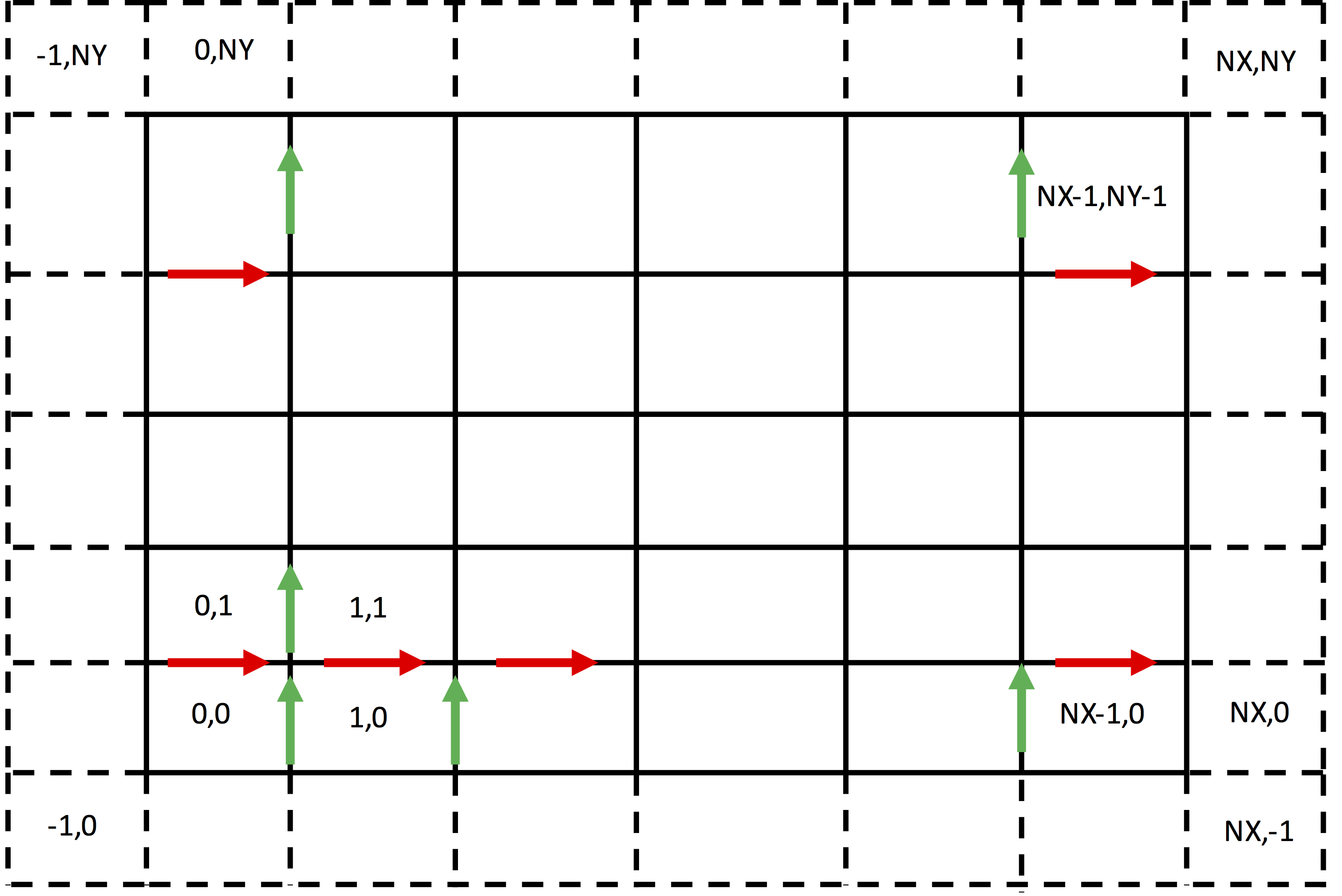
The update region is over the interior of the simulation. This varies for different components of the electric field and is illustrated in Fig. 41. The electric field in the x direction, shown in red, lies on x edges. The interior x edges have lower-left cell of (0,1) and upper-right cell of (NX-1,NY-1). In Vorpal, the region is greater than or equal to the lower bounds and less than (not equal to) the upper bounds. Hence, the update slab for \(E_x\) is [(0,1),(NX,NY)]. By similar reasoning, now referring to the green arrows, the update slab for \(E_y\) is [(1,0),(NX,NY)].

Fig. 41 Update region for the electric field.
For the magnetic fields, there is a similar difference in the update region per component. The magnetic fields are face fields, and so they are updated on any face that is in the interior or on a boundary.
When dielectrics are present, Maxwell’s equations need to be modified. Ampere’s equation gives the new value of the displacement, \(D\), from which one obtains the new value of the electric field, \(E\) by multiplication by an effective inverse dielectric tensor. Accurate algorithms for the time domain are described in [WBC13, WC07], while a more rigorous, but frequency domain algorithm is described in [BWC11].
Electromagnetic Slab Boundary Conditions
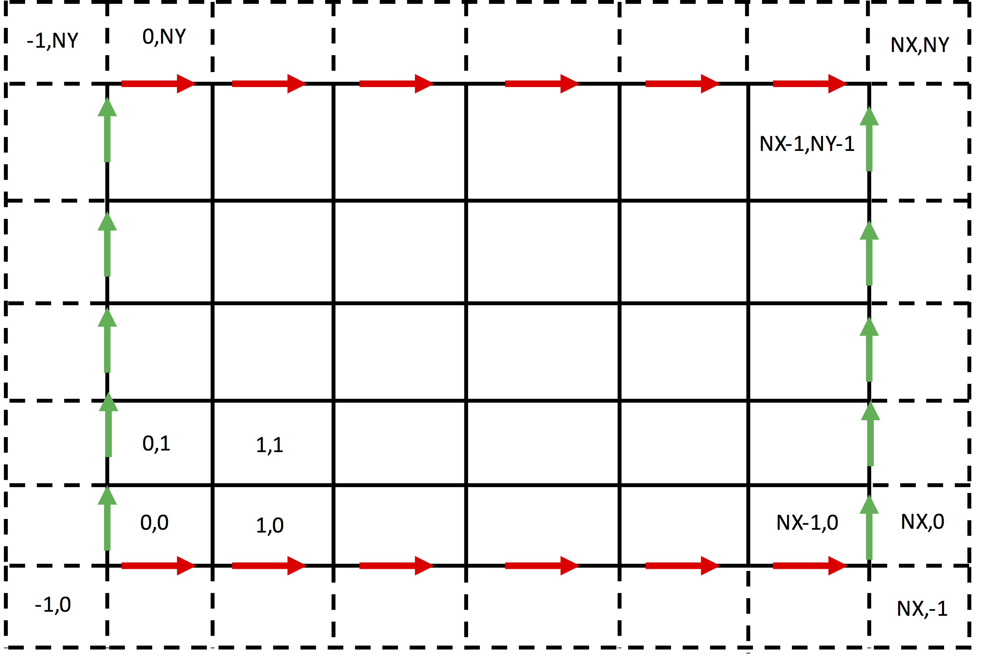
Beyond the edges of the simulation, values of the electric field are not known. Hence, one cannot update the electric field at the edge, as that would require a difference with an unknown value. Instead one sets boundary conditions. For the simple case of a purely rectangular region, the boundaries that must be set are shown in Fig. 42.

Fig. 42 Slab boundary regions for the electric field.
They are simply the tangential values of the electric field on the boundary. Just as in continuum EM, one need not set boundary conditions on the magnetic field. Setting the values of the tangent electric field at boundaries is sufficient.
Electromagnetic Conformal Boundary Conditions
Electromagnetic boundary conditions are to some degree setting the value of the electric field, but they can also involve a modification of how the magnetic field is updated.

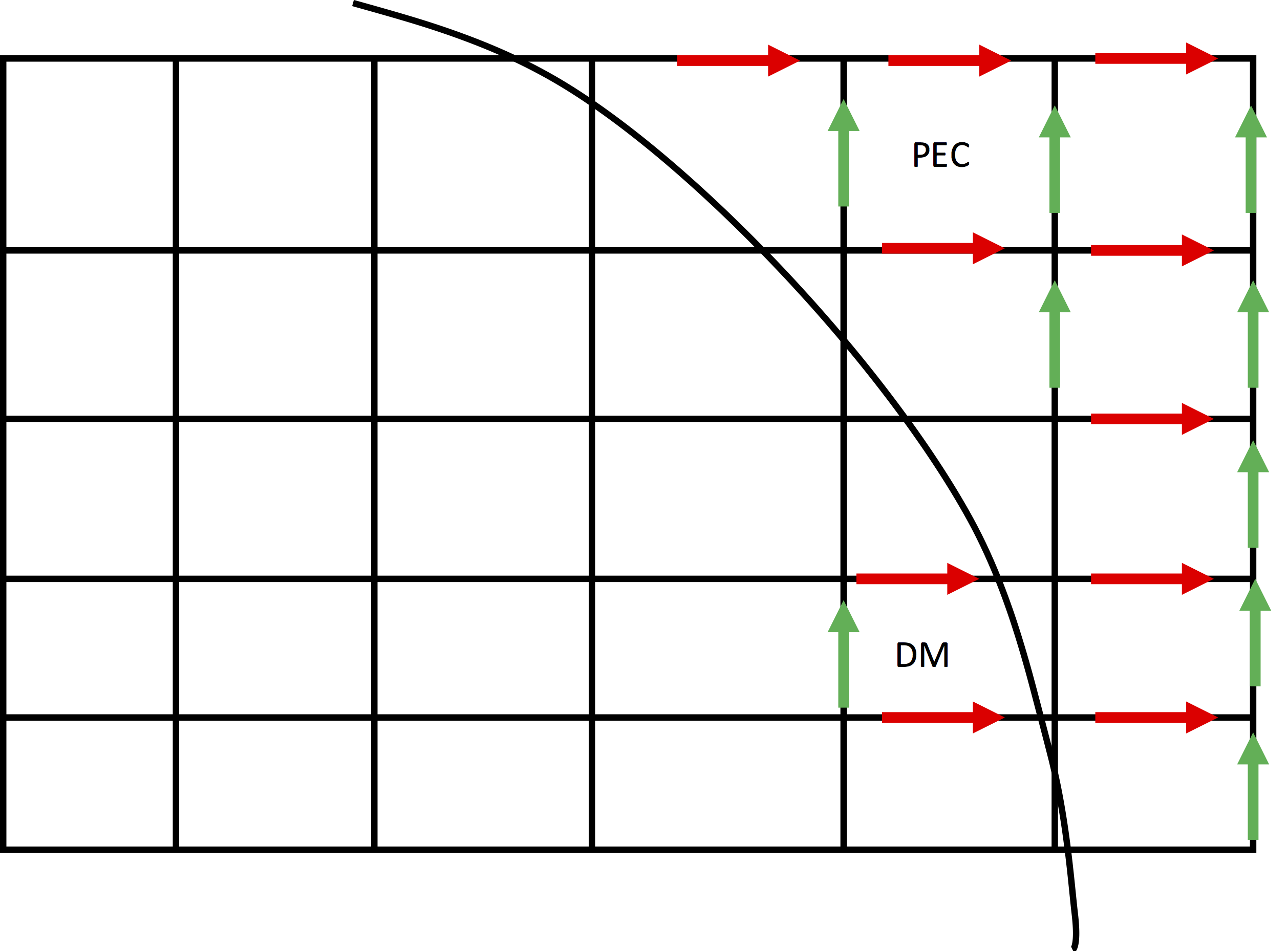
Fig. 43 Conformal boundaries for the electric field.
In Fig. 43 is shown a curve the interior (lower and left) of which is vacuum, while outside is Perfect Electric Conductor (PEC). All electric fields on edges that are totally in the PEC are set to zero. Then there are two approximations. In the stair-step approximation, one additionally sets to zero all electric fields whose edges are more than half outside. In the Dey-Mittra [DM97] algorithm, one starts by keeping any electric field on an edge even partially outside of the PEC. One then updates the magnetic field by using a line integral around the cell to get the change in magnetic flux, and then dividing that by the area of the part of the cell outside of the PEC. For the cell marked DM in Fig. 43, this would consist of adding up the marked electric fields (two in the x-direction and one in the y-diretion) with appropriate signs. Because of the area divisor, the Dey-Mittra algorithm can be unstable for time steps smaller than the uniform-grid CFL time step limit, and the smaller the area of the cell, the more the time step is limited. In practice, one sets an amount of acceptable reduction of the time step, and then one can compute the fractional cell areas that must be dropped [NCW+09].
Electrostatics
Electrostatics refers to finding the fields by a different mechanism. The electric and magnetic fields are still present. However, the magnetic field is static and imported, while the electric field at each time step is found by first solving for the potential, which satisfies Poisson’s equation,
and then finding the electric field from
which becomes finite differencing in numerics. Because we cannot directly state the solution for the potential, \(\phi\), but instead we have to solve for the potential, this is an implicit update. Therefore, solving Poisson’s equation involves setting up finite difference equations which leads to a system of equations. The system of equations is solved by inverting a matrix at each time step and solving the unknown (\(\phi\)) using the source term (\(\rho\)). The default value of the dielectric constant (\(\epsilon\)) corresponds to that of a vacuum. However, SpaceTimeFunctions can be defined to specify regions in which the dielectric constant differs from a vacuum, which can then be inserted into the Poisson Solve.
Electrostatic Slab Boundary Conditions
Poisson’s equation, upon discretization connects 2*D+1 grid nodes, as shown by the nodes within the curve in Conformal boundaries for the electric field.. Because this stencil reaches to each side of the node, it cannot be applied to edge nodes (covered by open circles). On those grids one must apply boundary conditions. For Dirichlet boundary conditions, one specifies the value of the potential on that node.
For Neumann boundary conditions, one specifies the value for the difference between the value of the potential on a node and the value on the node just interior. In general one must take care not to specify a mathematically impossible situation. As applied to Neumann boundary conditions, one cannot, e.g., specify zero Neumann boundary conditions on all surfaces while having non-zero net charge in the interior, as that would violated Gauss’s law. Similary, if one has a simulation that is periodic in all directions, consitency requires that it contain no net charge. Further, the matrix is singular unless one sets the value of the potential on at least one node.
Electrostatic Conformal Boundary Conditions
As this is an extensive subject, we simply say that for the nodes interior to a surface of constant potential, one specifies that the potential on that node, rather than being related to nearby points, is simply given. Otherwise one constructs the matrix as before.
Solving Poisson’s equation
Upon discretization and applying all boundary conditions, numerically one is left with a large matrix equation to be solved. There are multiple ways to do this within XSim, with direct or iterative solvers. This is discussed in more detail in Selecting Solvers and Solver Parameters.