- DomainDecomp
DomainDecomp
Determines the domain decomposition and periodicity. The DomainDecomp block determines how the simulation is broken up into domains for parallel processing and which directions are periodic.
If the domain boundaries lead to a specification of a number of processors that is not found at runtime, Vorpal will reconfigure the domain decomposition to match the runtime number of processors. That is, if you do not specify a decomposition, Vorpal will try to calculate an appropriate domain decomposition for you.
Vorpal is designed to run on a variety of systems, from a personal computer to a supercomputing cluster with hundreds of compute nodes. To accomodate the latter, Vorpal uses a hierarchical decomposition where the domain is first split equally along compute nodes (if running on a cluster), then split along the processors on each node. The DomainDecomp block determines the Inter-node decomposition, and the IntraNodeDecomp sub-block determines the decomposition within nodes. If running on a single compute node or personal computer, the IntraNodeDecomp can be omitted unless a manual decomposition is desired.
The regular decomposition algorithm used by Vorpal proceeds by first doing a prime factorization of the number of processors. It then uses that list of factors to divide up each dimension using the largest remaining factor on the dimension with the largest number of cells.
For example, for a simulation using 30 processors on a single compute
node and a domain size of 200 x 100 x 100, Vorpal will perform
the following calculations:
30 = 5*3*2
The x direction has the largest number of cells (200) and 5 is the largest factor of the number of processors, so we divide x into 5 regions, each
40x100x100
With the x direction done, y is the now the direction with the largest number of cells (100), so Vorpal uses the next largest factor to divide it into 3 sections:
40x{33 or 34}x100
Finally, Vorpal partitions z with the remaining factor is 2, dividing it into 2 pieces.
40x{33 or 34}x50.
That is the size of our final domains.
In practice, for parallelism, Vorpal simulations should have approximately 20 - 40 cells in each dimension. Otherwise, the amount of messaging per computation increases and the benefits of using multiple processors is outweighed by the cost of the communication between them. The 20 - 40 rule depends on the complexity of the calculations being done. With a large number of particles per cell (20 or more) you could use approximately 20 cells in each direction.
The decomposition may affect what features can be used; for example, guard cells require a domain of at least four cells in every direction. If the number of processors and dimensions of the simulation chosen cause this requirement to be violated, you will see errors in the simulation.
DomainDecomp Parameters
- kind (string)
regularand manual.
- periodicDirs (integer vector, optional, default = [])
Directions to have periodic boundary conditions.
- allowedDirs (integer vector, optional, default = [0 1 2])
Directions along which to split between compute nodes. If no IntraNodeDecomp block is present, also sets the allowed splitting for the domain on each node.
- IntraNodeDecomp (block, optional)
Specifies the decomposition between processors on the compute node or PC. If omitted, a regular decomposition with the above allowedDirs is performed. See IntraNodeDecomp
- ComputeNode (block, optional)
Specifies a manual decomposition for each ComputeNode (corresponds with hardware nodes). Required kind=manual for these to be used. ComputeNode block must specify lowerBounds and upperBounds (int vector) attributes. ComputeNode blocks have and optional attribute intraNodeDecomp (string, optional) that specifies the intraNodeDecomp block that should be used to decompose the node further. If this is not specified, a default intraNodeDecomp will be used.
Example of Default Decomposition Generation
In this example, Vorpal uses the aforementioned algorithm (prime
factorization) to automatically generate a decomposition for a parallel
simulation. The y- and z- directions will be periodic as indicated
by use of periodicDirs.
<DomainDecomp decomp>
  kind = regular
  periodicDirs = [1 2]
</DomainDecomp>
Example of User-specified Decomposition
In this example, assuming there is a 200 x 200 mesh grid as described
in the section on Grid cell specification, the user requests domain
boundaries in the x-direction at 50, 100, and 150, and in the
y-direction for 100 (expressed as fractions of the indicated domain
length). This will produce 8 domains, requiring that 8 processors
be used for the simulation. If the simulation is perfomed in 3D and
16 processors are used, Vorpal will further subdivide the domain
in half along the z- direction unless specifically disabled by
setting allowedDirs = [0 1] in the IntraNodeDecomp block.
Otherwise, if the actual number of processors used is not divisible by
the requested boundaries, Vorpal will default to the auto-generated
(prime factorization) decomposition as discussed in the general
description of DomainDecomp, above.
<DomainDecomp decomp>
  kind = regular
  periodicDirs = [1 2]
  <IntraNodeDecomp xyDecomp>
    kind = sliced
    cpuXFracs = [0.25 0.5 0.75]
    cpuYFracs = [0.5]
  </IntraNodeDecomp>
</DomainDecomp>
Example of full manual Decomposition
In this example, we assume there is a 240 x 240 mesh grid. Due to computational complexity in the middle of the domain, the user wants more processors focused there with less around the edges (e.g. high density of particles at center). The decomposition can be manually specified with each core assigned a slab via upper and lower bounds. The figure below shows the desire decomposition, and the block below shows the required decomposition block to perform this decomposition on a single compute node.
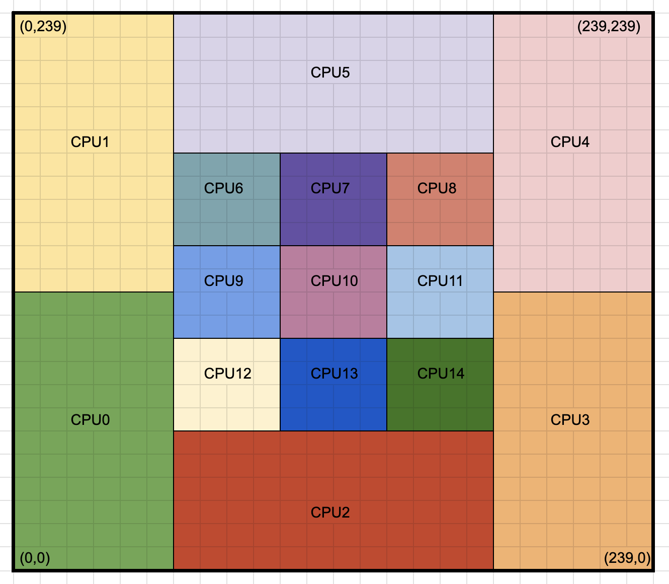
Fig. 131 Manual decomposition of a 240x240 simulation with higher concentration of cores in the center of the domain.
<DomainDecomp decomp>
  kind = manual
  periodicDirs = [0 1]
  <ComputeNode node0>
    lowerBounds = [  0    0 ]
    upperBounds = [ 240   240 ]
    intraNodeDecomp = node0decomp
  </ComputeNode>

  <IntraNodeDecomp node0decomp>
    kind = manual
    <NodeCpu cpu0>
      lowerBounds = [ 0  0 ]
      upperBounds = [ 60  120 ]
    </NodeCpu>
    <NodeCpu cpu1>
      lowerBounds = [ 0  120 ]
      upperBounds = [ 60  240 ]
    </NodeCpu>
    <NodeCpu cpu2>
      lowerBounds = [ 60  0 ]
      upperBounds = [ 180  60 ]
    </NodeCpu>
    <NodeCpu cpu3>
      lowerBounds = [ 180  0 ]
      upperBounds = [ 240  120 ]
    </NodeCpu>
    <NodeCpu cpu4>
      lowerBounds = [ 180  120 ]
      upperBounds = [ 240  240 ]
    </NodeCpu>
    <NodeCpu cpu5>
      lowerBounds = [ 60  180 ]
      upperBounds = [ 180  240 ]
    </NodeCpu>
    <NodeCpu cpu6>
      lowerBounds = [ 60  140 ]
      upperBounds = [ 100  180 ]
    </NodeCpu>
    <NodeCpu cpu7>
      lowerBounds = [ 100  140 ]
      upperBounds = [ 140  180 ]
    </NodeCpu>
    <NodeCpu cpu8>
      lowerBounds = [ 140  140 ]
      upperBounds = [ 180  180 ]
    </NodeCpu>
    <NodeCpu cpu9>
      lowerBounds = [ 60  100 ]
      upperBounds = [ 100  140 ]
    </NodeCpu>
    <NodeCpu cpu10>
      lowerBounds = [ 100  100 ]
      upperBounds = [ 140  140 ]
    </NodeCpu>
    <NodeCpu cpu11>
      lowerBounds = [ 140  100 ]
      upperBounds = [ 180  140 ]
    </NodeCpu>
    <NodeCpu cpu12>
      lowerBounds = [ 60  60 ]
      upperBounds = [ 100  100 ]
    </NodeCpu>
    <NodeCpu cpu13>
      lowerBounds = [ 100  60 ]
      upperBounds = [ 140  100 ]
    </NodeCpu>
    <NodeCpu cpu14>
      lowerBounds = [ 140  60 ]
      upperBounds = [ 180  100 ]
    </NodeCpu>
  </IntraNodeDecomp>
</DomainDecomp>